Traction System Electrical Components for Tri-brid Masaccio Trains in Italy
Highlight
With progress on carbon neutrality becoming ever more urgent as climate change worsens, railways have come to be recognized as a form of transport with a low impact on the environment. Meanwhile, Hitachi Rail has developed and supplied its Masaccio multimodal rolling stock based on a contract with Trenitalia S.p.A., an Italian railway operator.
The Masaccio is Europe’s first “tri-brid” train, able to run on overhead wires, diesel engine generators, or traction batteries. Capable of four different operating modes, the Masaccio can keep fuel consumption to a minimum by switching between different modes for each section of track.
This article presents an overview of the Masaccio’s features and traction system configuration along with plans for the future.
1. Introduction
Masaccio rolling stock are single-deck trains that operate in various regions of Italy (see Figure 1). Based on a contract with the Italian railway operator Trenitalia S.p.A., Hitachi, Ltd. has supplied the rolling stock in HTR312 and HTR412 configurations with three and four cars, respectively. Commercial services using the new trains commenced in December 2022 with the nickname “Blues.” Hitachi has also supplied Trenitalia with Caravaggio double-deck rolling stock in the ETR421 and ETR521 configurations that feature four and five cars, respectively. These commenced commercial operation in June 2019 with the nickname “Rock.” Figure 2 shows photographs of the Masaccio and Caravaggio. Both trains were manufactured through a partnership between Hitachi and the Italian division of Hitachi Rail, a group company within Hitachi’s railway systems business.
The Masaccio is Europe’s first “tri-brid” train, able to run on overhead wires, diesel engine generators, or traction batteries and equipped with four different operating modes. It is able to operate as an electric train by drawing power from 3,000-V direct current (DC) overhead wires when running on electrified track, and on the diesel engine generators, traction batteries, or both when running on non-electrified track.
This article presents an overview of the Masaccio’s features, the electrical components of its traction system, and the tri-brid system.
Figure 1—Regions of Italy where Masaccio Services Operate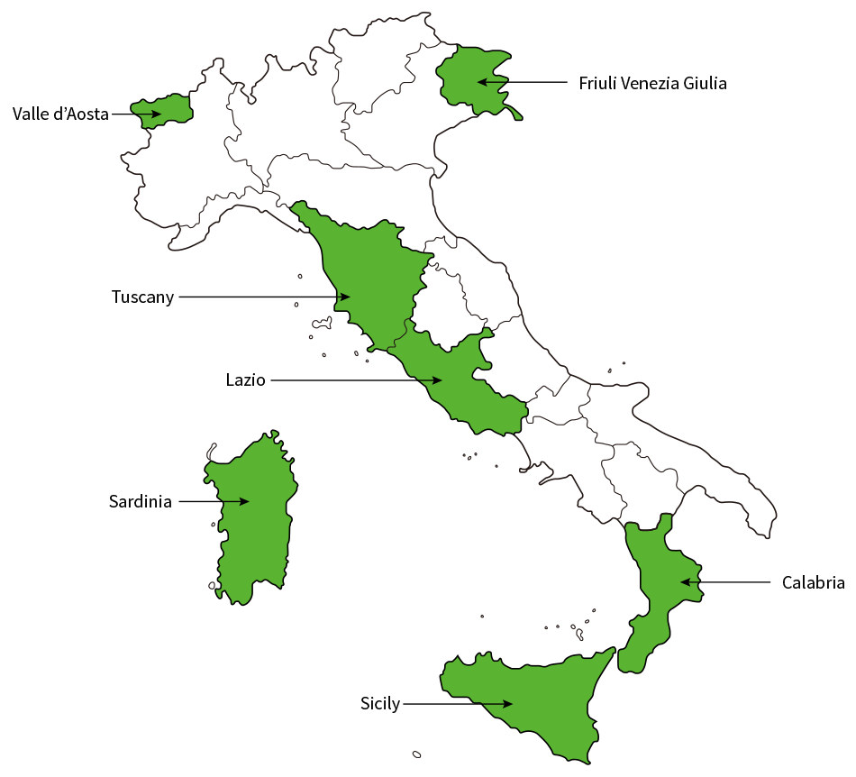 The map shows the regions of Italy where Masaccio rolling stock operate.
Figure 2—Hitachi Rail Rolling Stock in Italy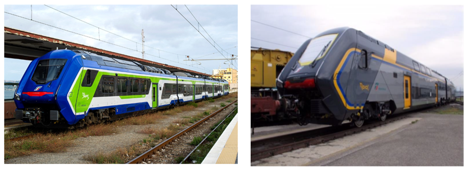 The photographs show the single-deck Masaccio (left) and double-deck Caravaggio (right).
2. Rolling Stock Features
Table 1 lists the specifications for the three-car configuration and Figure 3 shows the corresponding rolling stock configuration.
As noted above, the Masaccio is a tri-brid train that can run on three different power sources, namely overhead wires, diesel engine generators, and traction batteries, and can switch between these depending on the type of track it is running on. The four available operating modes are electric multiple unit (EMU) mode using DC3,000-V overhead wires, diesel-electric multiple unit (DEMU) mode using the diesel engine generators, hybrid multiple unit (HMU) mode using the diesel engine generators and traction batteries, and battery electric multiple unit (BEMU) mode using the traction batteries only.
The traction system components include traction converter, diesel engine generators, traction batteries, high-speed circuit breakers, traction motors, and the pantograph. All three of the power sources are connected to a common DC stage in the traction converter, with the DC3,000 V overhead wires being connected via the pantograph and high-speed circuit breakers, the diesel engine generators via alternating current/direct current (AC/DC) converters that convert three-phase AC to DC, and the traction batteries via DC/DC converters that converts DC to the required DC power supply. The DC stage supplies the final stages of the system, namely the inverters and auxiliary power supplies (APSs).
Table 1—Specifications of Three-car Configuration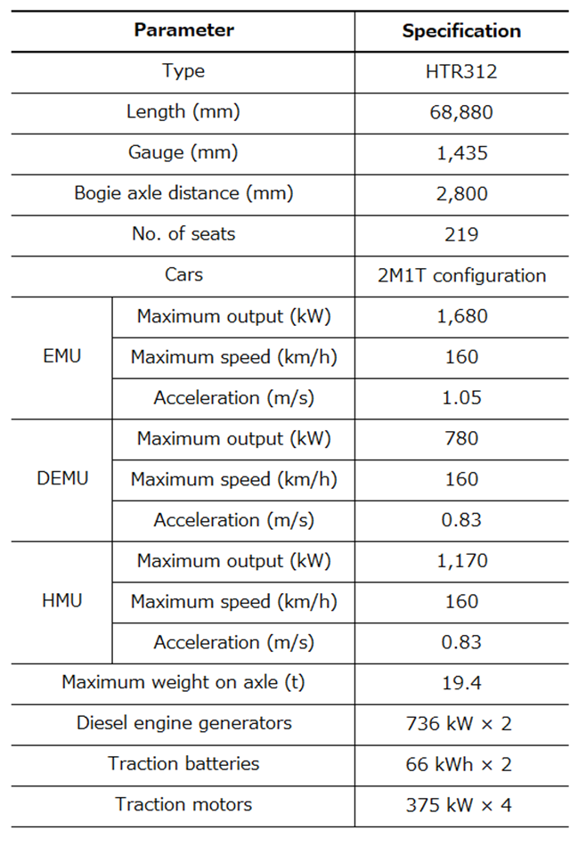 2M1T: two motor cars/one trailer car, EMU: electric multiple unit, DEMU: diesel-electric multiple unit, HMU: hybrid multiple unitThe table lists the specifications and performance of the Masaccio in its three-car configuration.
Figure 3—Three-car Configuration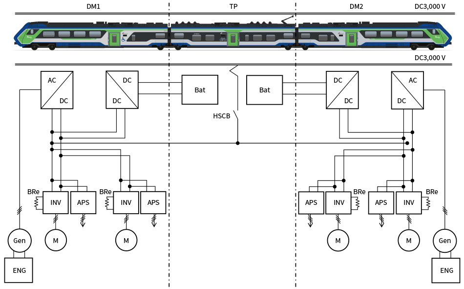 AC: alternating current, APS: auxiliary power supply, Bat: battery, Bre: brake resistor, DC: direct current, ENG: diesel engine, Gen: generator, HSCB: high-speed circuit breaker, INV: inverter, M: motorThe figure shows the traction system components housed in each car of the Masaccio in its three-car configuration.
3. Overview of each Component
Figure 4 shows photographs of traction system components, namely the (1) Traction converter, (2) Diesel engine generator, and (3) Traction battery. The following section overviews each of these components.
- Traction converter
The AC/DC converter for the diesel engine generator and the DC/DC converter for the traction battery, the inverter for the 3 KV DC [2 × 1C1M (one control unit/one motor)], brake chopper, APS, DC reactor, contactors, and sensors are all housed together in single boxes that are located on top of the DM1 and DM2 cars. - Diesel engine generator
The diesel engine generators each have a maximum output of 736 kW and are located under the floors of the DM1 and DM2 cars. - Traction battery
Each car has two traction battery modules, each with a capacity of 66 kWh and a nominal voltage of 718 V. The traction battery modules use lithium-ion batteries. They are water cooled, with each module able to be cooled using coolant supplied from the other module’s cooling unit based on information from their internal temperature management system. The traction batteries are located on the roof of the TP car.
Figure 4—Drive System Components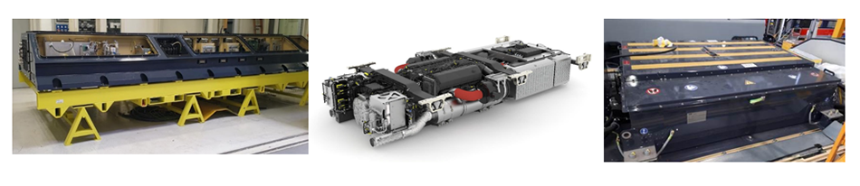 The photographs show the traction converter (left), diesel engine generator (middle), and traction battery (right).
4. Overview of Tri-brid System
4.1 Energy Flow in Each Operating Mode
Figure 5 shows the energy flows for each of the tri-brid system operating modes. The operation in each case is as follows.
- EMU mode
The power source used to power the train draws from the connection to the DC3,000 V overhead wires. The traction battery is charged using the power from the overhead wires or from regenerative braking. - DEMU mode
The power source used to power the train draws from the connection to the diesel engine generator. The traction battery is charged using the power from the generator or from regenerative braking. - HMU mode
The power source used to power the train draws from the connections to both the diesel engine generator and traction battery. The traction battery is charged using the power from the generator or from regenerative braking. - BEMU mode
The power source used to power the train draws from the connection to the traction battery. The traction battery is charged using the power from regenerative braking.
Figure 5—Energy Flows in each Operating Mode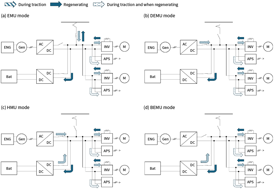 BEMU: battery electric multiple unitThe diagrams show the energy flows in each of the Masaccio’s operating modes.
4.2 Switching between Power Sources
Power source switching between the overhead wires, diesel engine generator, and traction battery is performed when the train passes from electrified to non-electrified track or vice versa, or when it approaches a railway station. The components used in the supply lines for each power source are operated in an appropriate manner to ensure that rapid power source switching is achieved without compromising safety or having a major impact on operation. Switching can be performed when the train is in motion, not just when stable.
The diesel engine generator and traction battery are used to supply power on non-electrified track without overhead wires, and these are connected to the common DC stages in the rolling stock’s traction converter, as explained above. Each control unit for the diesel engine generator and traction battery is equipped with automatic voltage regulators (AVRs) that maintain the target voltage to keep the voltage of the DC stage constant even when the voltages of the power sources fluctuate. To prevent conflict between the two control units that both control the same DC stage, the system is equipped with a function that selects which of the control units to use for AVR control depending on the power source, switching between these based on commands from the rolling stock control management system that monitors the entire rolling stock.
4.3 Diesel Engine Stop-Start Function
To maximize the amount of time spent running on traction battery power, the system is equipped with a function to turn the diesel engine off or on based on the rolling stock and operational circumstances. The function operates in the following cases.
- In the vicinity of a railway station
- When stable at a terminal station or depot
- When traveling between the depot and operating track
- When running on the traction battery only
Figure 6 shows how the function works in the vicinity of a railway station. This reduces noise, fuel consumption, and CO2 emissions by turning off the diesel engine and running on the traction battery only when close to a station or in a built-up area.
Figure 6—Engines Stop-Start at Railway Station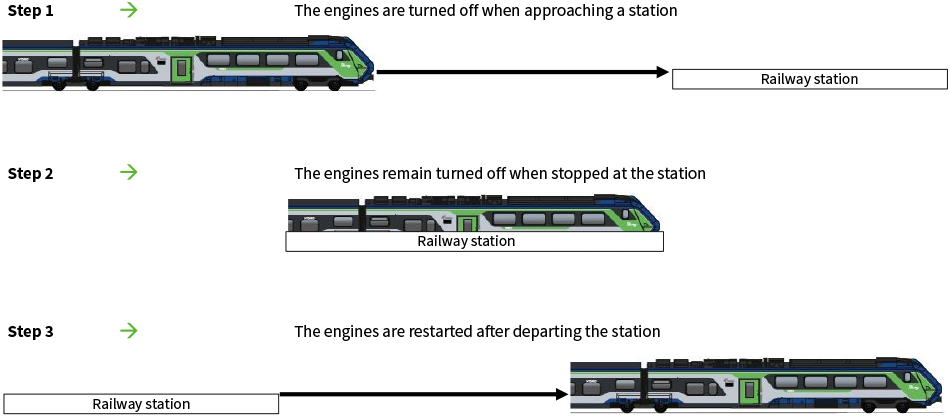 The diagram shows the timings for the start-stop function of the diesel engines that operates when the train is in the vicinity of a railway station.
5. Conclusions
This article has presented an overview of the Masaccio’s features, the electrical components of its traction system, and the tri-brid system.
In the future, Hitachi intends to contribute to carbon neutrality by replacing the diesel engine generators in rolling stock with traction batteries to reduce their CO2 emissions and fuel consumption.