
Development of Traction System for 273 Series DC Express Train
Highlight
The 273 Series DC express train has entered service as a new style of express train that was developed to further improve the safety, passenger services, convenience, and ride comfort of the Yakumo express that runs on the Hakubi Line of the West Japan Railway Company linking the San’in and San'yō regions of Japan.
This article describes the development of the traction system and how it was made smaller and lighter with improved energy efficiency. These improvements were achieved through the adoption of full SiC modules for the train control systems and revisions to the design of the cooling system for the traction motors to deal with the reduced availability of space for internal fittings that resulted from the adoption of a tilting-train pendulum configuration. Development work included a control technique for backward rolling starts together with highly accurate speed-sensorless control to ensure reliable vehicle control even on steep gradients.
1. Introduction
Figure 1—273 Series DC Express Train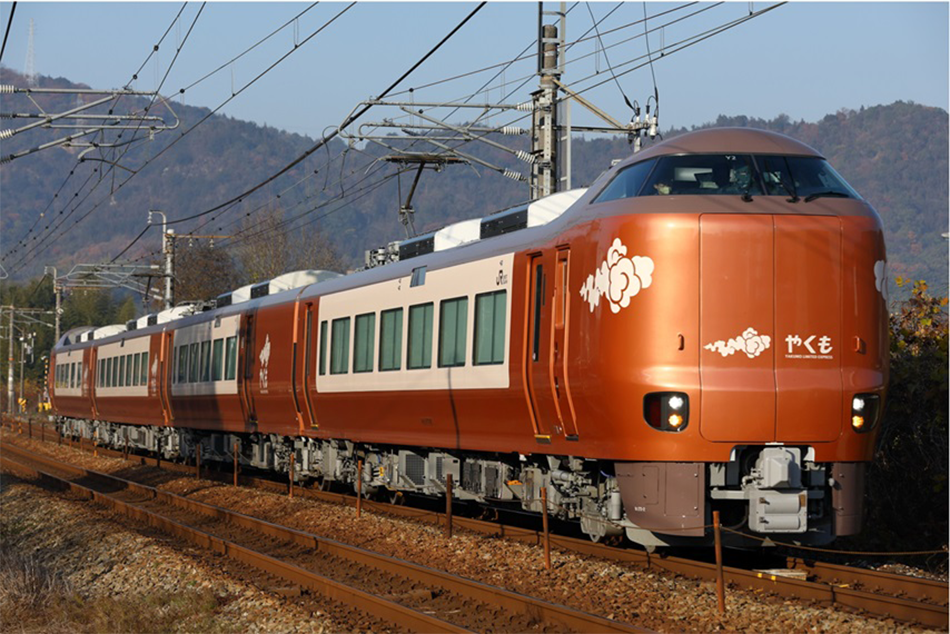 This photograph shows the 273 Series undergoing performance trials.
The 273 Series direct-current (DC) express train has entered service as a new style of express train (see Figure 1). Developed to further improve safety, passenger services, convenience, and ride comfort, the 273 Series is used by the West Japan Railway Company (JR West) on the Yakumo express that runs between the San’in and San'yō regions of Japan, replacing the 381 Series that first entered service back in the days of the national railway.
The 273 Series features a revised design for the traction motor cooling system to deal with the reduced availability of space for internal fittings that resulted from the adoption of a pendulum (tilting train) configuration and the adoption of full silicon carbide (SiC) modules for the variable-voltage variable-frequency (VVVF) inverter and static inverter (SIV) power units used by the train control systems. These features make the train smaller and lighter and improve its energy efficiency. System development also considered a control technique for backward rolling starts together with highly accurate speed-sensorless control to ensure reliable vehicle control even on the steep gradients found on the Hakubi Line where the new rolling stock will primarily be used.
2. Traction System
2.1 Overview
The train has a 0.5 M traction system, the primary configuration used by JR West since the 321 Series. All cars in the train are equipped with a VVVF inverter that controls the two traction motors and a train control system with a built-in SIV. Each train has four train control systems with a 1:1 two-motor/two-trailer (2M2T) configuration.
The VVVF power units use full SiC modules to make them smaller and lighter with improved energy efficiency. In a first for JR West, the SIV power units also use full SiC modules to further reduce size and weight.
As on the 323 Series, 227-1000 Series, and 271 Series, fully enclosed induction motors are used for traction drive. In addition to reduced cabin noise, these also ease maintenance by allowing bearings to be replaced without disassembly. Similarly, the use of unforced cooling eliminates the need for a dedicated blower to supply air and for internal ducting.
In terms of control functions, vector control is used on the VVVF inverter, the same as on other rolling stock since the 321 Series. Moreover, speed-sensorless control is also used, and the vehicle speed (rotor frequency) is calculated by the control unit of the VVVF inverter. By eliminating the need to attach a pulse generator (PG) to the traction motor to measure its speed, this makes for easier maintenance while also helping to increase motor capacity and decrease its size.
2.2 Speed-sensorless Control
2.2.1 Principle of Operation
This section explains how the speed-sensorless control works on the 273 Series.
While a number of different techniques have been proposed for speed-sensorless control, something most of them have in common is that they utilize the induced voltage generated in the motor. The voltage applied to the motor (inverter output voltage) is determined from the product of the drive frequency (inverter frequency) and the magnetic flux setting. Inputting this voltage generates an internal magnetic flux in the motor and this in turn results in an induced voltage that is determined by the product of the flux and rotor frequency. The torque current (≃ the current that flows in the rotor) is dependent on the difference between the inverter output voltage and this induced voltage. Accordingly, if this torque current is known, it can be used to back-calculate the difference between the inverter frequency and rotor frequency. By doing so, a rotor frequency estimate can be obtained.
2.2.2 Issues with Speed-sensorless Control
Unfortunately, the way that speed-sensorless control estimates the speed of a motor from its induced voltage means there is a range in the vicinity of zero motor speed where speed estimation is difficult. This is because the accuracy of the output voltage becomes relatively poor in this speed range and this results in a large estimation error. This has posed considerable difficulties for speed control when traction is engaged while the train is rolling backwards. This happens when the brake is released for a train on an upward gradient, causing it to start rolling backwards before the throttle (notch setting) is engaged to start the train moving uphill. As backward rolling starts on steep gradients need to be done smoothly for reasons of safety and reliable operation, work has been progressing on more accurate speed-sensorless control since the technique was first adopted on the 321 Series.
If a backward rolling start is not accomplished successfully, the train may lose track of the speed and continue to move backwards, resulting in the operation of the protection system and engagement of the emergency brake. Even if a backward rolling start is successfully accomplished, it can be detrimental to safe and reliable operation if the discrepancy between the estimated and actual train speed is large as this may result in excessive current flow in the VVVF inverter and extreme vehicle vibration.
As much of the Hakubi Line where the 273 Series operates runs through mountainous terrain with long sections of curved or steep track, improving its control performance for backward rolling starts is especially important.
Also, control is becoming more difficult year by year as the traction motors being used now are notable for their low slip rate compared to the motors on the 321 Series where speed-sensorless control was first introduced.
2.2.3 Implementation of Backward Rolling Start Control
As a train performing a backward rolling start after having halted on a sloping track will be moving backward when the control function is invoked, it will need to pass through the operating range described above where speed estimation is difficult. While this is basically done by generating an estimate of rotor frequency obtained by a feed-forward method, the system also operates in such a way as to increase the magnetic flux to ensure reliable traction drive with the required amount of torque.
Figure 2—Relationship between Slip Angle Frequency and Torque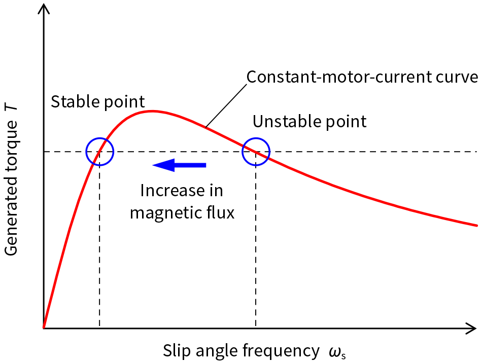 The control technique works by increasing the magnetic flux to shift operation to the stable point.
Figure 3—Constant-motor-current Curve and Operating Point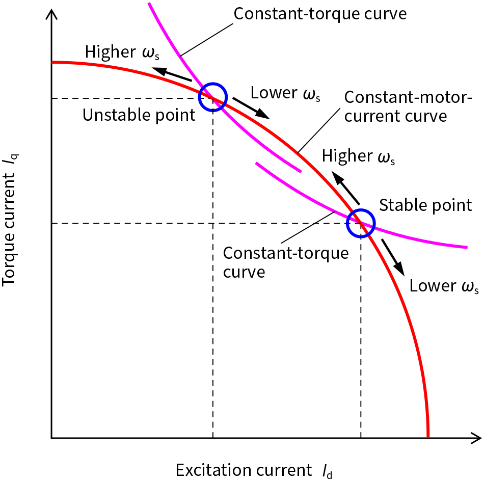 At the stable point, an increase in slip angle frequency increases the torque.
This increase in magnetic flux is achieved as follows. The torque generated by an induction motor can be expressed in terms of the slip angle frequency and the motor current. Figure 2 shows the relationship between slip angle frequency and torque when current control is used to maintain a constant motor current and Figure 3 shows the relationship between the constant-motor-current curve and constant-torque curve.
In Figure 3, the constant-motor-current curve follows a circular path and the constant-torque curves indicate the relationship between the excitation current and torque current that result in constant torque near each operation point. If magnetic saturation is ignored, the constant-torque curve is inversely proportional.
Consider the case when the estimated rotor frequency obtained by feed-forward is higher than the actual rotor frequency and the slip angle frequency is higher than intended. As current control is being used to maintain a constant motor current, the operating point moves in an anti-clockwise direction along the arc of the constant-motor-current curve. As the operating point is below the constant-torque curve at the unstable point, the torque decreases, reducing the acceleration, and thereby increasing the error in rotor frequency estimation.
At the stable point, in contrast, an increase in slip angle frequency moves the operating point above the constant-torque curve, increasing the torque and acceleration and thereby reducing the error in rotor frequency estimation. That is, it acts in such a way as to drive the system back to the operating point.
By controlling backward rolling starts in this way, increasing the magnetic flux shifts motor operation toward the stable point and reliable acceleration is maintained by controlling the motor in such a way that the actual rotor frequency tracks the feed-forward estimate of rotor frequency.
In practice, it is also necessary with induction motors to consider magnetic saturation when determining the operating point for this control technique. The control state transitions that occur when performing a backward rolling start are as follows. If the train is found to be moving backward when the initial speed estimate is obtained, the backward rolling start control mode is invoked and the technique for increasing magnetic flux is used. Once the train speed has accelerated past zero the increase in magnetic flux ends and normal control resumes.
The accuracy of the initial speed estimate after starting the train is an important factor in control stability when performing a backward rolling start. To improve this accuracy, the 273 Series uses full SiC modules for better measurement of the inverter output voltage. This is described in the next section.
2.3 Adoption of Full SiC Modules
The VVVF inverter and SIV power units in the 273 Series rolling stock use full SiC modules equipped with SiC metal-oxide-semiconductor field-effect transistors (MOSFETs).
Full SiC modules enables high power density and is used in the form of 2-in-1 modules that have two semiconductor modules each. This helps to make the train control system smaller and lighter as the full SiC modules have a mounting footprint that is approximately 50% less than equivalent-capacity silicon insulated-gate bipolar transistor (Si-IGBT) modules.
While device switching deadtime (turn-off to turn-on time) varies depending on the magnitude of the current, another feature of full SiC modules is that this variability is smaller than it is for IGBT modules.
That is, another benefit of the low-variability full SiC modules is higher accuracy when estimating the initial speed under low-current conditions. Whereas the error in speed estimation tends to be greater for IGBTs that suffer from higher deadtime variability, the low-variability full SiC modules are less prone to this problem.
2.4 Power Units
As in the 271 Series and other rolling stock, the 273 Series uses full SiC modules in its VVVF inverter power units. In a first for JR West, it also uses full SiC modules in its SIV power units.
Whereas an integrated power unit was used for the VVVF inverters and SIVs in rolling stock such as the 271 Series that were introduced prior to the 273 Series, the 273 Series has separate VVVF inverter and SIV power units. This was done to improve redundancy and facilitate power unit management and maintenance. While the capacities of the full SiC modules used in the power units are optimized to suit the VVVF inverter and SIV respectively, the same basic hardware design has been adopted for both power units to enable the higher-capacity VVVF inverter power unit to be used to power the SIV (the reverse is not possible).
2.5 Characteristics of Train Control System and Reductions in Size and Weight
Because of the many curves on the Hakubi Line where the 273 Series rolling stock is used, a tilting-train pendulum body configuration was chosen for improved ride comfort. As achieving this required a reduction in the area taken up by underfloor equipment, the size of the train control system needed to be shrunk in both the longitudinal and lateral dimensions.
In addition to the size and weight savings provided by the full SiC modules described above, this was done through further system optimization and downsizing accomplished by adopting digital controls in the driver’s cab to eliminate metal wiring (by consolidating control communications) and optimizing the unit hardware in the housing (including by eliminating unnecessary equipment and preparatory work). To ensure ease of maintenance and operation, however, the design also sought to retain commonality with the 271 Series and other existing rolling stock for equipment such as high-speed switchgear and circuit breakers.
Figure 4 shows the WPC19-(H) train control system for the 273 Series.
Similarly, Table 1 shows a comparison with the train control system used in the existing 271 Series. The housing size has been reduced by 15% and the equipment weight by 13% while delivering the same VVVF and SIV capacities as before.
Figure 4—WPC19-(H) Train Control System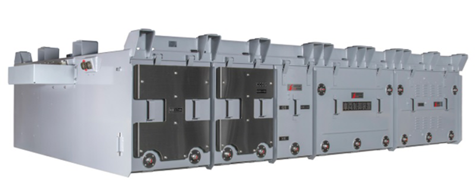 The size and weight have been reduced by enhancements that include use of SiC modules.
Table 1—Comparison of Train Control System Specifications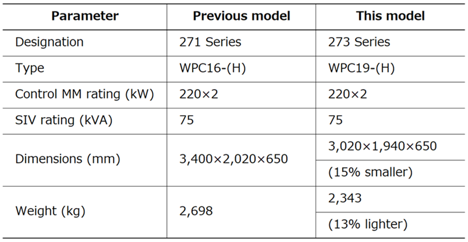 The size has been reduced by 15% and the weight by 13% while still maintaining the same control capacity as the previous model.
2.6 Traction Motor
As traction motors are installed in the bogie they must be designed to fit in the space available. While JR West has a standard wheel diameter of 860 mm (at maximum), the pendulum bogie configuration used on the 273 Series requires a smaller 810-mm (maximum) wheel diameter. This places further constraints on the available space. Accordingly, as it was not possible to continue using the fully enclosed traction motors from the 271 Series, the motor needed to be shrunk by more than 7% without reducing its output.
Shrinking the size of a traction motor without changing its output means increasing its power density (output/weight). The problem with this, unfortunately, is that it leads to higher temperatures for reasons that include the increased losses associated with the higher current needed to maintain the same output and the degradation in cooling performance that results from shrinking the motor. Overcoming this calls for design measures that will improve the electrical efficiency of the traction motor to reduce the losses, or improvements to cooling performance that will prevent temperature rise. For the 273 Series, cooling performance was improved by adopting a fully enclosed motor configuration with an external fan that uses counter-flow cooling, a first for JR West. This increased the power density by 25% compared to Hitachi’s standard fully enclosed traction motor, sufficient for it to be installed in a pendulum bogie (see Figure 5).
Table 2 provides a comparison of key traction motor specifications.
Figure 5—WMT110 Traction Motor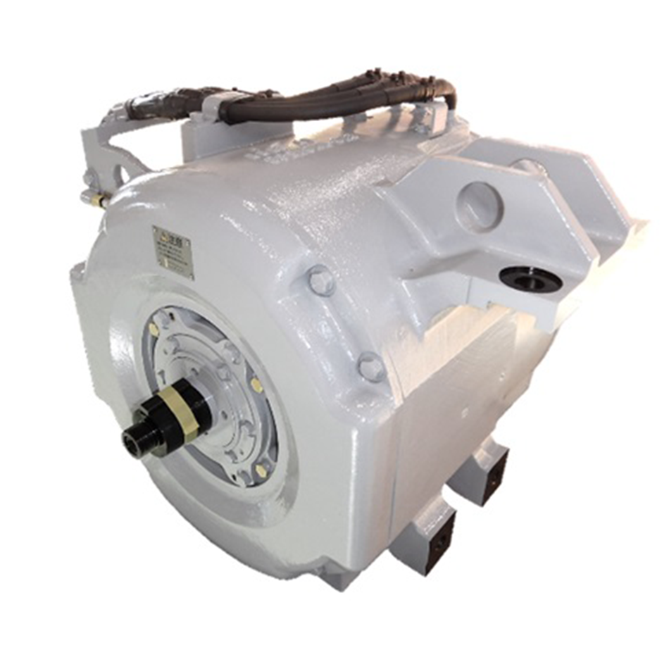 The size of the motor was reduced by using counter-flow cooling.
Table 2—Comparison of Traction Motor Specifications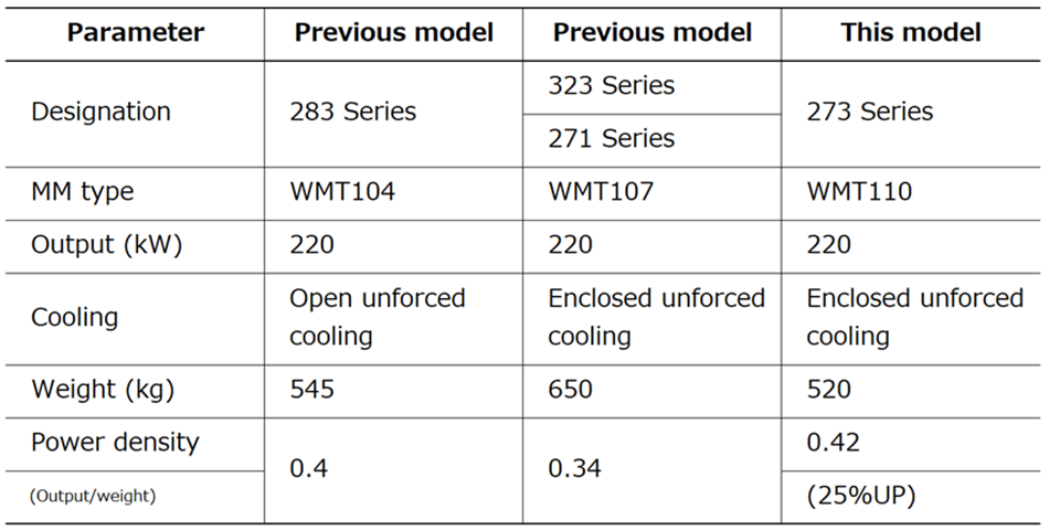 The power density was increased by 25% over the previous model to enable the motor to be installed in pendulum bogies without reducing its output performance.
3. Performance Evaluation
The new traction system was installed in 273 Series rolling stock and on-track testing was conducted to evaluate its performance.
3.1 Results of Traction and Braking Tests
Traction and braking tests were conducted to verify that the traction performance and regenerative braking performance conformed to the design values. The results indicated good control of both traction and regenerative braking with no problems such as abnormal fluctuations in current or voltage.
3.2 Results of Temperature Testing
Table 3—Results of Measuring Temperature Rise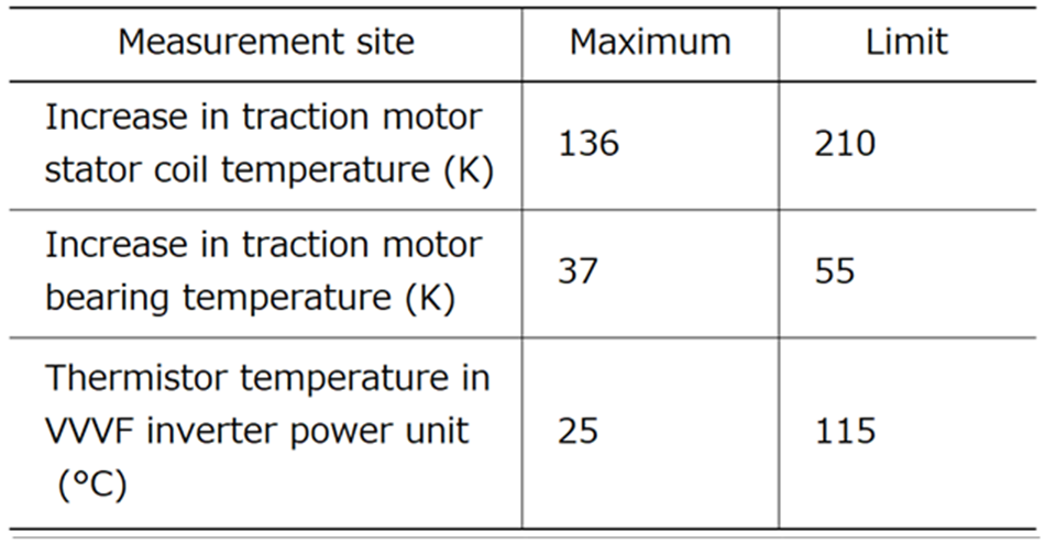 The results show that the temperatures remained below the limit during a return trip with one unit disengaged.
To verify that the temperatures of the VVVF inverter power units and traction motors did not exceed the design limits, temperature measurements were conducted for a return trip between Izumoshi and Okayama stations, part of the line where the 273 Series operates. The measurements were taken both on a train in full working order and with one of the units (1 × train control system and 2 × traction motors) disengaged (1.5M2.5T).
Table 3 lists the test results. These show that the temperatures of both the VVVF inverter power unit and traction motors remained within the design limits.
3.3 Results of Testing Incline Starts (Backward Rolling Starts)
Table 4—Conditions for Testing Incline Starts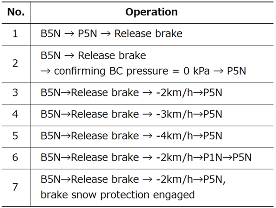 Control performance was evaluated by testing incline starts under a range of operating conditions.
Figure 6—Results of Testing Incline Starts (Backward Rolling Starts)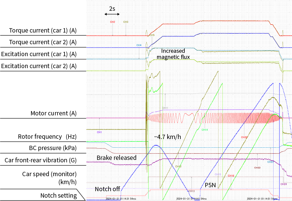 The graph shows the results of testing on a 25‰ incline using the sequence, B5N→release brake→-4 km/h→P5N.
Testing to verify the performance of the control technique for backward rolling starts was conducted by starting the train on an incline (a backward rolling start) on a section of the Hakubi Line between Shingō and Shōyama stations where there is a continuous gradient. This incline start testing was evaluated for a number of different locations and test conditions (see Table 4). The gradients tested were 25‰, 15‰, and 5‰. Here, 25‰ is the maximum gradient on the line whereas a gradient of 5‰ results in the backward rolling start occurring while the speed is still close to zero, the range where estimating the initial speed is difficult. Testing was conducted both on a train in full working order and with one of the units disengaged (1.5M2.5T) to replicate a case where the train control system is faulty.
Figure 6 shows a typical chart from testing. The brake was released and the train started rolling backwards before control was initiated, which occurred at a speed of about -5 km/h. Nevertheless, the initial estimation accuracy of the reverse-direction speed was good and increasing the magnetic flux resulted in steady acceleration, with the transition to normal control taking place after the speed turned positive again.
Several dozen tests were conducted for each set of conditions. In all instances, the train reliably started to climb and no incline start failures occurred. The tests also demonstrated good control performance, with no excessive vehicle vibration or torque shocks at any of the phases (starting while rolling backwards, passing through zero speed, or accelerating).
The main factors in the ability of the 273 Series to perform backward rolling starts are as follows.
- Reliable backward rolling starts are made possible by adjusting operation such that an appropriate torque is used to increase the estimated speed while in the zero-speed region where speed estimation error is large, thereby making it easy to transition past this difficult zero-speed region.
- The use of full SiC modules reduces deadtime variability and this improves the accuracy of initial speed estimation.
- Speed estimation accuracy has also been improved by drawing on experience from previous rolling stock and other expertise to set optimal control settings.
4. Conclusions
Development of the traction system for the 273 Series accomplished the following three outcomes.
- Development of a train control system that is small enough to fit in the constrained cross-section of the pendulum body configuration. This was achieved by using full SiC modules in its VVVF inverter and SIV power units.
- Development of a traction motor small enough to be used with small-diameter 810-mm wheels. This was achieved by adopting a fully enclosed motor configuration with external fans and counter-flow cooling.
- Development of precise speed-sensorless control able to perform reliable backward rolling starts even on steep inclines, and the demonstration of this capability.
The 273 Series commenced operation as the Yakumo in April 2024. There are currently 11 trains in commercial operation, designated Y1 to Y11. They are expected to remain in use on the Hakubi Line for many years to come.
REFERENCES
- 1)
- Seiji Tsuruoka, et al., “Overview of Yakumo 273 Series DC Express Train,” Japan Railway Engineers' Association, Vol.67 (May 2024) in Japanese.
- 2)
- Tesuo Kojima, et al., “Practical Deployment of Vector Control without Speed Sensor: Stabilization of Acceleration at Low Speeds Using Zero-speed Torque Control,” Proceedings of Railway Cybernetics Symposium (Nov. 2004) in Japanese.