
Hitachi’s Efforts in the Nuclear Sector (5)Environment Improvement Technologies for Decommissioning of Fukushima Daiichi Nuclear Power Plant
Highlight
Ensuring a good working environment both inside and outside the Fukushima Daiichi Nuclear Power Plant is vital if the task of removing fuel debris is to proceed safely and effectively. To this end, equipment has been developed for removing heavily contaminated water from the reactor cooling water system to reduce the radiation levels in high-dose-rate areas inside the reactor building. To deal with the hydrogen that builds up in the cooling water pipes, an electrolytic polishing drilling technique that does not risk ignition was used to make holes in pipes so that a hose equipped with a self-propulsion mechanism could be inserted into the cooling water system. This has been used in work undertaken to remove heavily contaminated water from Unit 1.
1. Introduction
More than a decade has passed since the Great East Japan Earthquake and during that time various survey and other preparatory work has steadily progressed toward the removal of fuel debris from Units 1, 2, and 3 at Fukushima Daiichi Nuclear Power Plant. Experimental removal from Unit 2 commenced in FY2024, marking the transition to phase 3 of the mid- to long-term roadmap1). Full-scale work on the removal of fuel debris is set to begin in due course. Ensuring a good working environment both inside and outside the power plant is essential if this work is to proceed safely and effectively. To help achieve this, Hitachi Group has developed a system for removing heavily contaminated water from the reactor cooling water system (RCW) to reduce radiation levels in high-dose-rate areas inside the reactor building. Work is progressing on getting this system working on the actual equipment (see Figure 1).
The falling of fuel debris to the bottom of the primary containment vessel (PCV) of Unit 1 is believed to have damaged the RCW pipes that run through this area, allowing contamination to spread widely inside the pipes. As a consequence, radiation levels are high throughout the pipes. In particular, the three RCW heat exchangers located adjacent to the access port for large equipment on level 2 of the reactor building contain large amounts of contaminated water2) with a high concentration of radioactive material. The ambient dose rate in their vicinity is 1,000 mSv/h or higher. The consequent exposure concerns for workers engaged in fuel debris removal work means that measures are needed to reduce radiation levels. One such action taken to help reduce radiation in the RCW heat exchangers was to use openings in the floor above (level B3 of the reactor building) to make holes in the heat exchanger inlet header pipes so that a hose could be inserted into the equipment to sample the contaminated water (see Figure 2)3).
In undertaking this work, however, it was not possible to rule out a build-up in the heat exchanger inlet header pipes of combustible gases (hydrogen) from the initial accident or generated by radioactive decay in the contaminated water. Accordingly, it was crucial that the holes in the pipes be made using a method that would not pose an ignition risk. To this end, an electrolytic polishing drilling technique was developed for creating holes in pipes that contain combustible gases by using a corrosion reaction to dissolve the pipe wall metal. This ensures that the potential ignition sources of friction, heating, and the buildup of static electricity pose less of a risk than using mechanical drilling. This technique was subsequently put into practice. A self-propulsion mechanism fitted with an active scope camera4) was also developed to get the hose into position in the heat exchanger.
This article describes the newly developed self-propulsion mechanism and electrolytic polishing drilling technique and the results of testing on a mockup of the actual plant.
Figure 1—Conditions on South Side of Unit 1 Reactor Building
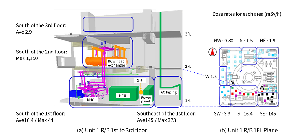 RCW: reactor cooling water system, HCU: hydraulic control unit, FL: floor Human access to the area around the RCW heat exchanger located on the south side of the second floor of the Unit 1 reactor building is difficult due to the very high ambient radiation dose rate of more than 1,000 mSv/h.
Figure 2—Method for Accessing RCW Heat Exchanger
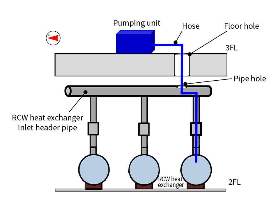 To provide an access route for inserting a hose into the RCW heat exchanger located on level 2 of the reactor building, holes were made in the floor above (level 3) and in the RCW heat exchanger inlet header pipes.
2. Development of Mechanism for Pipe Access
To remove the heavily contaminated water from the RCW heat exchangers, it was first necessary to insert a hose through holes made in the level 3 floor and in the RCW heat exchanger inlet header pipes and to thread the hose through the curves in the pipes and through the manifold plate at the inlet of the heat exchanger until it reached the bottom of the heat exchanger.
Figure 3 shows how this pipe access mechanism works. The three main parts are an end piece, the body of the hose, and an active scope camera that is fitted inside. As shown in (a) and (b) in Figure 3, the body of the hose includes a mechanism with active wheels and passive joints that is attached to the exterior hose and provides steering control for the end of the hose. This exterior hose is coated with hair-like fibers (cilia). Vibration of these hair-like fibers provides the propulsive force. That is, the active scope camera is equipped with an electric motor between the fiber-coated external and internal hoses such that the vibration of this motor imparts a driving force to the fibers, as shown in Figure 3 (c).
Figure 3—How Pipe Access Mechanism Works Using Active Scope Camera
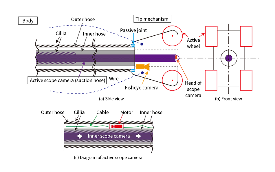 Figure 3 (a) shows a cross section of the mechanism, (b) shows a front view, and (c) shows a detailed diagram of the internal scope camera. The three main parts of the mechanism are an end piece, the body of the hose, and an active scope camera that is mounted internally. The end piece includes active wheels that are used both to control the position of the hose tip and to drag the hose body along. The active scope camera is coated with hair-like fibers and vibration is used to provide propulsive force.
Figure 4 shows how the mechanism was used to gain access to the interior of the pipes. After being inserted through the opening in level 3 of the rector building, the mechanism then traveled along a horizontal pipe (the inlet header pipe for the RCW heat exchanger). In addition to using the vibration of the hair-like fibers to provide propulsive force, the direction of travel could also be controlled by adjusting the speed of the wheels in the end piece. By doing so, the end piece was maneuvered to the desired location (at the top of the target heat exchanger) and then lowered down. After the linear and rotational action of the passive joints and active wheels were used to position and orient the mechanism correctly, as shown in Figure 4 (b), the internal hose was inserted via the target hole and pushed down from the manifold plate to its intended final position, as shown in Figure 4 (c). Once the hose was in position, a sample of heavily contaminated water was collected. Finally, a wire was used to pull the mechanism out, as shown in Figure 4 (d). This task was facilitated by vibration of the hair-like fibers, which reduced resistance and made the mechanism easier to pull out.
Figure 4—Method for Accessing Pipe Interior
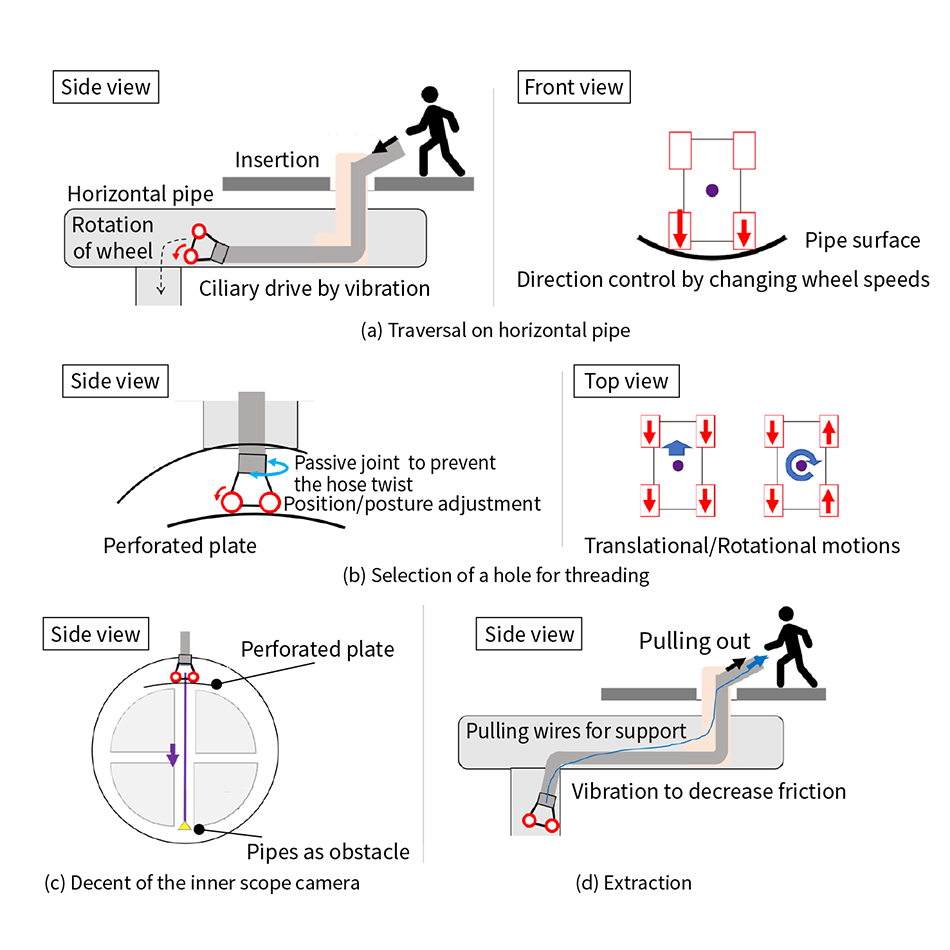 Figure (a) shows the mechanism traveling along a horizontal pipe, (b) shows how it gets to the correct insertion position, (c) shows insertion of the internal hose, and (d) shows how the mechanism is removed. The mechanism is inserted into a horizontal pipe, the end piece is driven to the desired location, and then the end piece is used to lower it.
Figure 5 shows the fabricated pipe access mechanism being used. After insertion through the opening in the floor of the reactor building, it is equipped with the ability to move itself along inside the horizontal pipe and align its position over the hole in the manifold plate at the heat exchanger inlet through which the internal hose is inserted.
Figure 5—Pipe Access Mechanism (Mockup Testing)
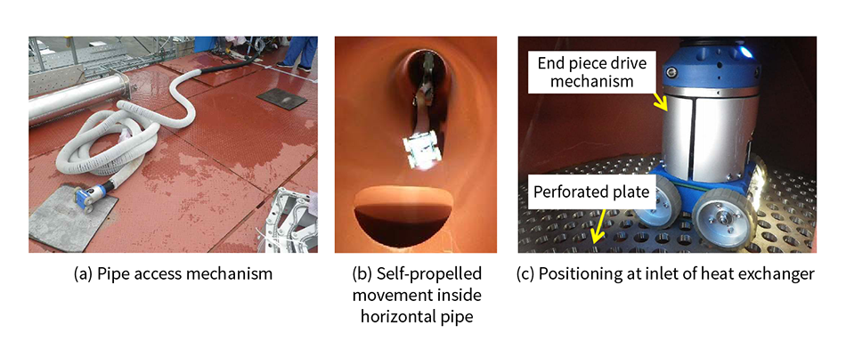 Photograph 5 (a) shows the pipe access mechanism, (b) shows it moving itself along a horizontal pipe, and (c) shows it being positioned at the inlet of a heat exchanger.
3. Use of Electrolytic Polishing Drilling Technique in Extraction of Contaminated Water to Reduce RCW Radioactivity
Work was undertaken to sample the heavily contaminated water in the RCW heat exchangers at Unit 1 for the purpose of developing a plan for water removal. To provide an access route for inserting a hose into the heat exchangers, an electrolytic polishing drilling technique was developed and implemented that uses a corrosion reaction to dissolve the pipe wall metal.
3.1 Development of Electrolytic Polishing Drilling Technique
While mechanical drilling is the usual method for making holes in pipes, it is necessary to avoid friction, heating, and the buildup of static electricity in pipes that contain combustible gases as these could cause the gas to ignite. Accordingly, Hitachi looked at ways of making holes in pipes by dissolving the metal wall and has developed an electrolytic polishing drilling technique that uses a corrosion reaction for this purpose that is accelerated by passing an electrical current between the pipe metal and an electrode via an electrolyte. Figure 6 shows how this works. The development process included parameter testing to determine the optimal operating practices, including what to use as the electrolyte, the voltage and current, and the distance between the pipe metal and electrode. Experimental testing was also performed to verify that the technique could be used on pipes containing hydrogen without igniting it. This testing used a prototype of the apparatus and was conducted using an explosion-proof facility at the National Institute of Advanced Industrial Science and Technology.
Figure 6—Use of Electrolytic Polishing Drilling to Provide Access Route into RCW Heat Exchanger
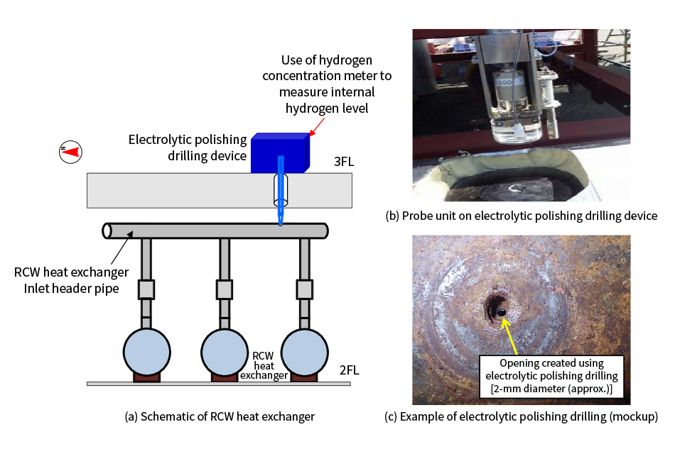 Figure 6 (a) shows how a hole is formed in the inlet header pipe in a schematic of the RCW heat exchanger, (b) shows the probe in the electrolytic polishing drilling device, and (c) shows a 2-mm hole through a mockup of an RCW heat exchanger inlet header pipe that was made by electrolytic polishing drilling.
3.2 Use of Electrolytic Polishing Drilling Technique on Actual Pipes
To enable electrolytic polishing drilling of RCW heat exchanger inlet header pipes at Unit 1, a device was fabricated for this purpose based on the knowledge obtained from parameter testing. Taking account of the practicalities of on-site use and the universality of pipes, the device was split into three separate units that could be connected together. These were a pump unit containing a pump and tank for recirculating the electrolyte, a hydrogen measurement unit with an instrument for measuring the level of hydrogen in the pipe after a hole has been formed, and a direct-current (DC) power supply unit. When this was used to perform electrolytic polishing drilling on one of the plant pipes, measurements taken through the resulting hole (about 2 mm in diameter) found the level of hydrogen to be about 72%3). This was lowered to below the ignition level for hydrogen (4% concentration) by repeated injection and ventilation of inert gas (N2 gas) through the electrolytic polishing drilling unit. A pipe hole cutting device was then used to open the hole up to 250 mm in diameter and the pipe access mechanism described above was used to insert a hose into the heat exchanger and take a water sample. As analysis of the water samples showed a maximum concentration of CS-147 of 3.20×10¹⁰ Bq/L2), this confirmed that the presence of contaminated water in the RCW heat exchanger was a cause of its high level of radioactivity. The intention is to use the information obtained from this work to formulate an action plan for water removal. To minimize worker exposure, these electrolytic polishing drilling and heat exchanger water sampling tasks were remotely controlled from a low-radiation area and included observation on a monitor screen and the collection of operational data.
4. Conclusions
This article has described the development of equipment and progress on its practical application for use in improving environmental conditions at Fukushima Daiichi Nuclear Power Plant by the removal of heavily contaminated water from the Unit 1 RCW to facilitate plant decommissioning. Further reductions in the level of radiation in the reactor building are needed to enable future work, including surveying and fuel debris removal, and this is also the case at Units 2 and 3. Accordingly, Hitachi intends to continue its development of environmental improvement technologies to ensure that decommissioning work can proceed smoothly over the long term.
Acknowledgements
The work described here on reducing RCW radiation levels at Unit 1 of the Fukushima Daiichi Nuclear Power Plant was undertaken under contract to Tokyo Electric Power Company Holdings, Inc. Moreover, the development of the electrolytic polishing drilling technique received considerable support from people at the energy and environmental sections of the National Institute of Advanced Industrial Science and Technology and the explosion safety and industrial safety research groups at its Research Institute of Science for Safety and Sustainability, and from the Japan Gas Association. Similarly, considerable support was also received from people at the Tough Cyberphysical AI Research Center at Tohoku University on robotics technology for the use of hair-like fibers (cilia) for propulsion that was incorporated into the pipe access mechanism developed for inserting hoses into heat exchangers to enable the sampling of water from the RCW heat exchangers. The authors would like to take this opportunity to express their sincere gratitude.
REFERENCES
- 1)
- Secretariat of the Team for Countermeasures for Decommissioning, Contaminated Water and Treated Water, “Outline of Decommissioning, Contaminated Water and Treated Water Management” in Japanese.
- 2)
- Tokyo Electric Power Company Holdings, Inc., “Sampling results of the Unit 1 RCW heat exchanger” in Japanese.
- 3)
- Tokyo Electric Power Company Holdings, Inc., “Analysis Results of Residual Gas Levels Prior to Work on Water Sampling at Unit 1 of Fukushima Daiichi Nuclear Power Plant to Reduce Radiation Levels in Reactor Cooling Water System (Water Removal)” in Japanese.
- 4)
- Yuichi Ambe, et al., “Development of a Telescopic Active Scope Camera that Threads Perforated Plates for the Decommissioning of the Fukushima Daiichi Nuclear Power Plant,” Proceedings of FDR2024 (International Topical Workshop on Fukushima Decommissioning Research)