
3D Digital Twin System for Remote Construction Work
Highlight
The construction industry has been under pressure in recent years to utilize DX to boost productivity. In pursuit of this digital approach to construction, Hitachi Plant Construction, Ltd. has been investigating remote techniques with the potential to boost efficiency at construction sites. While past efforts in this area have involved operating remote-control machines by viewing the images from the networked cameras with which they have been equipped, this work requires a high degree of skill and experience.
With the goal of eliminating skill requirements, Hitachi has addressed this issue by developing a 3D digital twin system that provides an intuitive sense of the locations and movements of remote-control machines at the construction site. By attaching sensors to remote-control machines and using a network connection to show their real-time movements and positions in a virtual space, this highly versatile system has the potential to ensure the safety of remote construction work.
This article gives an overview of the 3D digital twin system and describes its main functions. It also reports on the results of verification trials and future plans.
Introduction
Decreasing numbers of experienced workers and a lack of interest among the young have become a concern for the construction industry in recent years. As demand for construction work is nevertheless expected to grow strongly in coming years, this workforce shortage is a severe problem. Improving the efficiency of on-site work in tandem with working style reforms also poses a challenge, calling for productivity improvements to be made through smart construction practices utilizing digital transformation (DX).
In response, Hitachi Plant Construction, Ltd. has been investigating remote construction practices for the purpose of reducing the amount of construction work and number of workers needed in ways that will directly benefit the efficiency of on-site work. “Remote construction” means substituting remote-control machines for workers and operating them from a remote location based on sensor measurements and data from cameras on the machines. A lot of development has gone into hardware and software for remote construction over recent years and initiatives have been reported involving a variety of construction sites1), 2).
Hitachi Plant Construction has used various forms of remote construction in the past, including remotely operated steel cutting and equipment installation3), 4). This work has involved installing cameras in the work area together with remote-control machines and operating the machines from a remotely located control room with the help of multiple camera images5). This remote operation was done safely by having the work supervisor pay careful attention to the camera images displayed on large screens in the control room while issuing instructions to the people operating the remote machines.
Unfortunately, a number of difficulties arise when remote work is done using feeds from multiple cameras. The first is that there is a limit to the number of locations where cameras can be installed, making it difficult to eliminate all blind spots during remote operation. It is also difficult to determine exactly how close the machine is to other nearby equipment. As a result, the work requires people with well-honed intuition and experience that gives them a sense of the overall behavior of the remote-control machine. It is also why the skill requirements of remote work need to be eliminated if remote construction is to be made more efficient.
Recognizing this need, Hitachi Plant Construction has set about developing a three-dimensional (3D) digital twin system that can serve as a visual support tool, giving users a multi-perspective and detailed sense of what is happening with the remote-control machines at a construction site.
This article gives an overview of the 3D digital twin system and describes its main functions. It also reports on the results of verification trials and future plans.
Overview of 3D Digital Twin System
Virtual Space Implementation and Self-positioning Acquisition
Figure 1 shows an overview of the 3D digital twin system.
First, the region around the robot, represented by a point cloud or computer-aided design (CAD) model, is replicated in virtual space and then overlaid with a 3D model of the robot. To create the virtual space in the 3D viewer from a point cloud or CAD model, a 3D viewer with the ability to replicate CAD models in this way was selected.
Next, sensor data from the site [see Figure 1(a)] is used to animate the 3D model of the robot in the virtual space [see Figure 1(b)]. This shows the actual arm joint angles, the vehicle orientation, and its location obtained by self-positioning. The robot self-positioning information used in the virtual space is obtained by simultaneous localization and mapping (SLAM) of the robot position and surrounding environment. The network used to exchange data between the machine in physical space and the 3D model in virtual space was implemented using Robot Operating System (ROS).
By updating the 3D model to match the actual robot in real time, these networks provide a synchronized 3D environment.
Figure 1—Overview of 3D Digital Twin System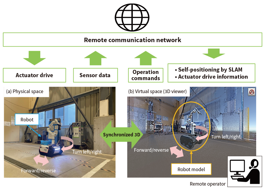 The region around the robot is replicated by a point cloud or CAD model and this is overlaid with a 3D model of the robot. The model in the 3D viewer is animated using data from the sensors on the remote-control machine that is sent via the network.
Feedback Control for Collision Avoidance
To ensure the safety of remote operation, it is important to prevent the remote-control machine from colliding with any nearby objects. For this purpose, a collision risk model was created that envelops the entire model of the remote-control machine in the 3D viewer by a specified margin. This was used to develop feedback control for collision avoidance that functions by sending a control signal to the remote-control machine, instructing it to slow down or stop if the collision risk model overlaps the model of the area surrounding the machine. Figure 2 shows how this works.
The collision risk model sizes are specified first. These take the form of two cylindrical shapes centered on the central axis of the robot vehicle [see Figure 2(a)]. If the static model of the surrounding area overlaps the machine stop region (inner cylinder), a control signal is sent via the network to the robot vehicle instructing it to stop. The robot also stops if a dynamic object (person or object) comes within its light detection and ranging (LiDAR) measurement range. Similarly, if the model of the surrounding area overlaps the machine deceleration region (outer cylinder), a control signal is sent via the network to the robot vehicle instructing it to slow down. Figure 1(b) and 1(c) show the robot slowing down and stopping when the model of the surrounding area overlaps the collision risk model. The function also uses its ability to detect intrusions into the respective regions to display the current status on the viewer screen (including whether the machine is slowing down, stopped, or has collided) based on the machine’s proximity to any other nearby equipment.
Figure 2—Overview of Feedback Control for Collision Avoidance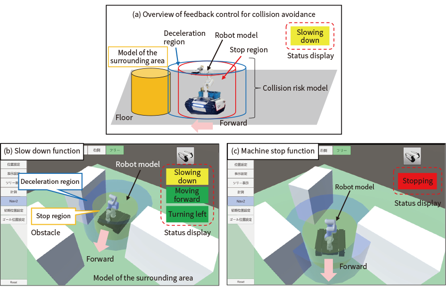 Diagram (a) shows how supervisory feedback control for collision avoidance works by the 3D viewer issuing commands to the robot whenever the model of the surrounding area overlaps the deceleration or machine stop regions of the collision risk model (which are specified in terms of relative distance). Screens (b) and (c) are examples of how the top right of the 3D viewer screen shows the current status (whether the machine is slowing down, stopped, or has collided) based on the machine’s proximity to any other nearby equipment.
Verification Trial
Overview
Testing was conducted to verify the 3D digital twin system and feedback control for collision avoidance. Figure 3 shows photographs of the remote-control crawler robot with attached manipulator that was used for this verification trial. The robot was equipped with encoders on each of the six manipulator joints, two encoders on the crawler drive wheels, a two-dimensional (2D) LiDAR was attached to its front end, and an inertial measurement unit (IMU) sensor was fitted at its center to measure the vehicle’s angle of tilt and the turning angle around its axis.
Figure 4(a) shows an overview of the trial mockup and Figure 4(b) shows an enlarged view of the objects to be manipulated. Networked cameras were installed in four locations. The verification trial involved grasping and removing sheet material by remote control. The sequence of steps was as follows.
- The robot travels from its starting position to the object to be picked up. The manipulator is then used to align the gripper (attached to the end of the manipulator) with the object [see Figure 4(a)].
- The gripper grasps the object and lifts it up [see Figure 4(b)].
The verification trial compared the performance of remote operation using the networked cameras on their own and using them together with the 3D viewer.
Figure 3—Robot Used in Verification Trial The robot was made up of a crawler [Bunker mini (supplier: Agile X)], manipulator [Xarm 6 (supplier: Ufactory)], 2D LiDAR [RPLiDAR S1 (supplier: Slamtec)], and IMU [WT61C (supplier: Witmotion)].
Figure 4—Verification Trial Mockup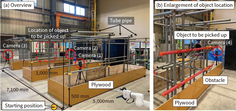 The mockup was made from tube pipe and plywood. The plywood was made 500 mm high to ensure that the 2D LiDAR (attached to the robot at a height of 300 mm) would be able to detect it.
Results
The networked camera images and 3D view screens were observed and the trial conducted by the method described above.
Figure 5 shows the 3D viewer screen and camera images for the part of the mockup trial where the robot traveled from its starting position to the object. Figure 5(a) is a 3D viewer screen showing a view of the mockup trial from above. This indicates how a bird’s eye view of the current position of the robot among the other equipment can be provided even when there is no camera installed on the ceiling.
Next, Figure 5(b) is a 3D viewer screen and Figure 5(c) is a camera image from when the manipulator was used to pick up the object with its gripper, which is attached to the end of the manipulator. The 3D viewer screen shows the robot avoiding a tube pipe obstacle. Also visible on the 3D viewer screen is the successful replication of the object being lifted up, following the same trajectory as the tip of the gripper. In Figure 5(c), the manipulator is shown having the same orientation at the same timing, demonstrating how the model in the 3D viewer maintains real-time synchronization with the robot.
These results demonstrate the utility of the 3D digital twin system for remote construction by confirming its ability to show the relative positions of the robot and surrounding equipment from any angle during operation.
The following describes the results of testing the feedback control for collision avoidance. Based on the size of the robot used in the trial, the deceleration region and (inner) machine stop region of the collision risk model, as described above, were chosen to be cylinders with diameters of 1,500 mm and 1,000 mm respectively, centered on the centerline of the model. Similarly, the response to an object intruding inside the deceleration region was specified as a reduction in speed to 0.20 m/s. This compares to the standard crawler speed of 0.35 m/s. Figure 5(d) shows the 3D viewer screen when the robot was slowing down or stopping due to an object coming within the (outer) deceleration region or (inner) machine stop region while the robot was moving forward. The trial confirmed that the crawler did decelerate and stop when this happened. It also confirmed that the robot remained stationary when inadvertently instructed to move forward after coming to a stop. The 3D viewer also correctly displayed the “Stopped” status on the top right of the screen.
These results demonstrate that feedback control for collision avoidance maintains the safety of remote construction as the robot will not collide with nearby equipment that is within the machine stop region, even if operated accidentally. The trial also demonstrated how it helps to eliminate skill requirements by using the 3D viewer screen to display the status of the robot (whether it is slowing down, stopped, or has collided) based on its proximity to nearby equipment.
Figure 5—3D Viewer Screens and Camera Images from Verification Trial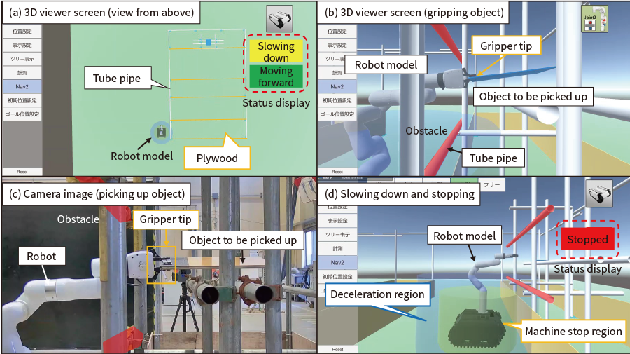 The screen in (a) shows a view of the mockup from above. The screen in (b) shows use of the 3D viewer screen to navigate the robot around a tube pipe. The image in (c) shows the robot at the time of the screenshot in (b). The position and orientation of the robot match those shown in (b) for that point in time. The screen in (d) shows the crawler behavior replicated in the 3D model, slowing down when a nearby item of equipment comes within the deceleration region, and stopping when the model of the surrounding area comes within the machine stop region.
Conclusions
With the goal of ensuring the safety of remote construction, Hitachi Plant Construction has developed a 3D digital twin system that can serve as a visual aid to remote-control operation. The highly versatile system works by attaching sensors to remote-control machines and using a network connection to show their real-time movements and positions in a virtual space. As a result, the system has the potential to keep remote construction work safe and eliminate skill requirements for remote operation.
In the future, Hitachi intends to use this versatile system for the remote-control operation of heavy machinery. Hitachi also intends to contribute to the future realization of safe remote construction by working with customers on the collaborative creation of new solutions that use these digital technologies.
REFERENCES
- 1)
- Shimizu Corporation News Release, “Collaboration between People and Robots Equipped with the Latest Technology at Construction Job Sites―Shimizu Smart Site, a Next-generation Production System―” (Jul. 2017)
- 2)
- Taisei Corporation News Release, “Development of T-iROBO Remote Viewer, a real-life remote imaging system” (Jan. 2017) in Japanese
- 3)
- Tokyo Electric Power Company Holdings, Inc., “Commencement of X Brace Removal (Cutting) Work at Unit 1 Reactor Building at Fukushima Daiichi Nuclear Power Plant” (Sept. 2018) in Japanese
- 4)
- Tokyo Electric Power Company Holdings, Inc, “Completion of Reinforcing Installation for Fuel Handling System at Unit 1 Reactor Building at Fukushima Daiichi Nuclear Power Plant on 2020/10/29 (Thur.)” (video archive) in Japanese
- 5)
- Tokyo Electric Power Company Holdings, Inc, “Completion of Reinforcing Installation for Fuel Handling System at Unit 1 Reactor Building at Fukushima Daiichi Nuclear Power Plant on 2020/10/29 (Thur.)” (images) in Japanese