
Development of Traction System for Rolling Stock Using Hydrogen Fuel Cells
Highlight
Goal 7 of the United Nations Sustainable Development Goals is “Ensure access to affordable, reliable, sustainable and modern energy for all.” Achieving this will require a global expansion of access to clean fuels and clean technologies along with further progress on integrating renewable energy for end-uses in buildings, transportation, and industry.
The railway sector likewise needs to reduce its carbon dioxide emissions and expand future energy diversity. To this end, Hitachi has partnered with East Japan Railway Company and Toyota Motor Corporation on the joint development of a drive system that incorporates fuel cells, including its use in trial operation.
This article describes the system configuration, equipment, and control techniques used on the FV-E991 testing car equipped with fuel-cells.
Introduction
To reduce carbon dioxide emissions and expand future energy diversity, Hitachi has partnered with East Japan Railway Company (JR East) and Toyota Motor Corporation on the joint development of the FV-E991 testing car equipped with hydrogen fuel cells. The project draws on rolling stock design and manufacturing technology from JR East, technologies for hybrid drive systems in trains that has been jointly developed by JR East and Hitachi, and the fuel cell technologies from Toyota’s work on the development of fuel-cell cars and buses. These technologies have been combined to deploy fuel cells commercialized for automotive use in a railway application, thereby creating a high-power drive system for rolling stock vehicles that are much larger than their automotive counterparts(1).
System Configuration
Figure 1 shows a photograph of the FV-E991 testing car and Table 1 lists its main specifications. Similarly, Table 2 lists the specifications for the fuel cell hybrid system(2), (3), (4), (5).
Figure 1—FV-E991 Testing Car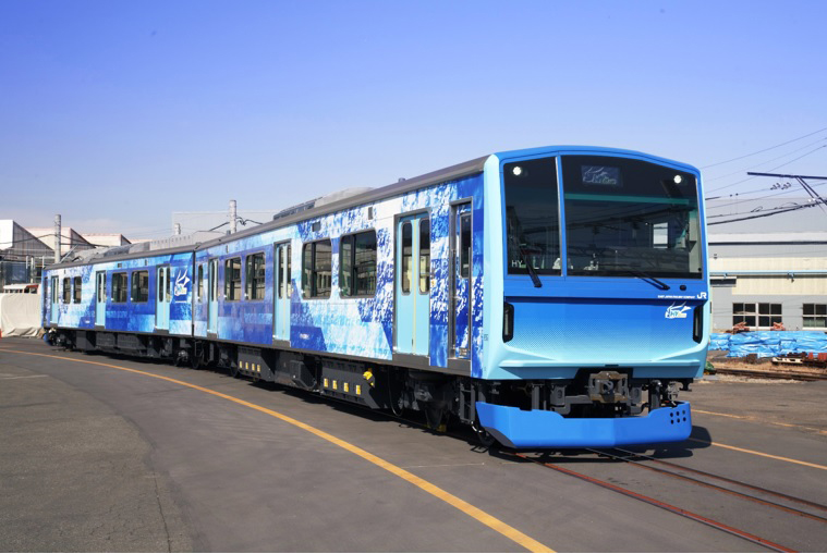 Photograph courtesy of East Japan Railway CompanyThe photograph shows the FV-E991 testing car equipped with hydrogen fuel cells. It has a fixed two-car configuration.
Figure 2—Block Diagram of Fuel Cell Hybrid System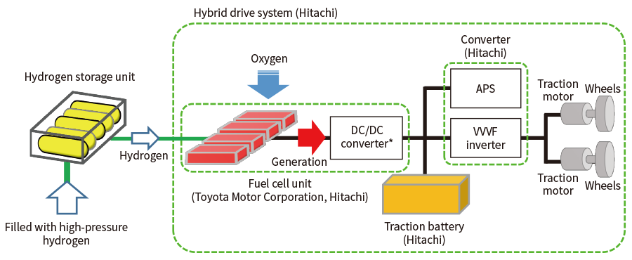 DC: direct current, VVVF: variable-voltage variable-frequency
* A device that adjusts the DC voltage from the fuel cell to match the traction battery voltage (DC).The system is based on fuel cells that use hydrogen as fuel to generate electric power and includes a traction battery to recover electric power from kinetic energy during braking.
Table 1—Main FV-E991 Specifications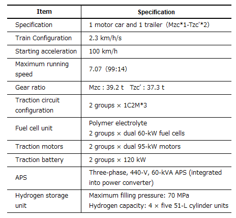 APS: auxiliary power supply
*1 Mzc stands for a motor equipped vehicle with driver cabin.
*2 Tzc stands for a trailer vehicle with driver cabin.
*3 C stands for controller and M stands for motor. 1C2M indicates that one VVVF inverter (controller) controls two motors. The system uses solid polymer fuel cells proven in automotive applications together with lithium-ion traction batteries.
Hydrogen from the hydrogen tank is supplied to the fuel cell where it is used to generate electricity through a chemical reaction with oxygen from the air. The traction battery is charged by the electric power from the fuel cell as well as by regenerative electric power from braking. The variable-voltage variable-frequency (VVVF) inverter drives the traction motor using electric power from both the fuel cell and the traction battery. The auxiliary power supply (APS) likewise draws electric power from both the fuel cell and the traction battery, supplying three-phase power at 440 V to the air conditioning system, compressors, internal lighting, and other auxiliary loads.
The FV-E991 is designed to provide traction performance similar to the HB-E210 diesel hybrid electric car that is used in the Sendai area. Figure 3 shows the powering tractive force tractive characteristics (fully loaded, 16 ton/vehicle). It is able to maintain an equilibrium speed of more than 100 km/h when traveling up a 3‰ grade. Similarly, the equilibrium speed for a 25‰ grade is 65 km/h.
The traction system components include the fuel cell, fuel cell high-speed circuit breaker (FCHB), traction battery, VVVF inverter, and auxiliary power supply (APS + transformer and filter circuit). For redundancy, the traction circuit is made up of two independent sets with an 1C2M*1 configuration. Figure 4 shows the traction circuit diagram for one of these sets. Similarly, the APS also has a redundant configuration that includes a standby unit to maintain train operation and onboard services in the event of an equipment failure. Switchover between APS systems is performed by three-phase switchgear (3ph CGS). Power is supplied to the onboard equipment from the active APS via the inverter transformer (IvTR). To prevent current resonance between the VVVF inverter and APS filter capacitor, a common charging circuit is used with direct connections to both devices. The fuel cell units are connected to the traction circuits via the FCHB. The FCHB operates as a protective circuit breaker if overcurrent occurs in the fuel cell system circuit.
Figure 3—Tractive Force Characteristics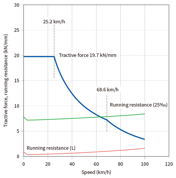 The rolling stock is designed to have running performance equivalent to a diesel hybrid train.
Figure 4—Block Diagram of Traction Circuit (One Set)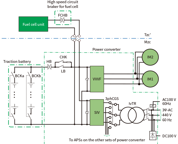 IM: induction motor, IvTR: inverter transformer, HB: high-speed current breaker, FCHB: fuel cell high-speed current breaker, 3ph CGS: three-phase switchgearThe configuration is based on a diesel hybrid system and combines a simple circuit with redundancy.
Equipment Overviews
Fuel Cell Unit
Figure 5—Photograph of Fuel Cell Unit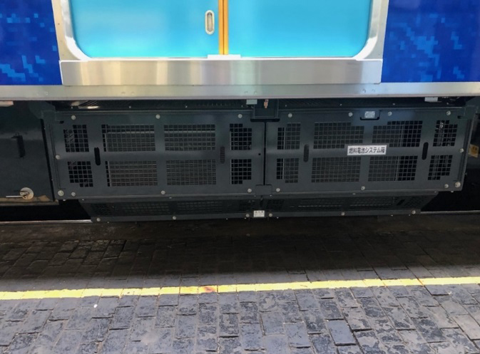 Each unit has two 60-kW modules. Two of the units (two sets) are installed on the Tzc car and these are fueled by hydrogen to generate the base electric power for the rolling stock.
Figure 5 shows a photograph of the fuel cell unit. Each unit contains two fuel cell system modules (60 kW each) that generate electric power from the hydrogen fuel and oxygen in the air. The fuel cell units incorporate a step-up chopper that steps up the stack voltage to ensure that electricity is generated reliably at the direct current (DC) voltage of the traction system. These units are cooled by water cooling system.
The fuel cell units also incorporate hydrogen detectors to identify any hydrogen leaks in the unit.
Toyota was responsible for the design and supply of the fuel cell system modules and other components, which are the same as those used in its fuel cell electric vehicles. The layout design and fabrication of the components and piping used in the fuel cell units were done by Hitachi with support from Toyota. Because each set of power converters has one fuel cell unit, the train has a total of two units in the Tzc’ car(5).
Power Converter
Figure 6—Power Converter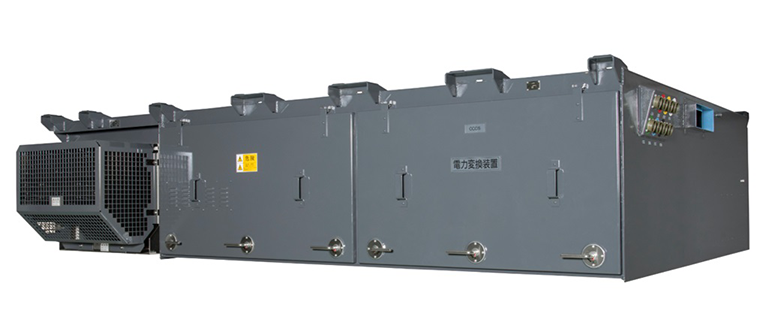 The converter in designed for small size and contains both the VVVF inverters and APSs. It handles control of the entire hybrid system, including the fuel cells.
Figure 6 shows the power converter. The converter is made up of two power units incorporating the VVVF inverter and APS, an alternating-current reactor (ACL) and alternating current capacitor (ACC) that together form an AC filter, the IvTR, 3ph CGS, and the APS circuit. These are all incorporated into a single housing to minimize the combined size of the traction circuit and APS circuit. The 3ph CGS allows for switching between the two APS sets, providing continuity of the 440-V three-phase power supply from the backup APS in the event of a failure of the active APS. However, both sets of power converters share the same inverter transformer and other equipment for output because of the low potential for its failure.
As electric circuit in the power unit requires the VVVF inverter and APS to be directly connected to prevent resonant currents, and as redundancy can be achieved by keeping the each set independent of the other, an integrated configuration was adopted in which the directly-connected VVVF inverter and APS are housed in the same power unit.
The size of the power units was also reduced by using all silicon carbide (SiC) modules which are equipped with metal-oxide semiconductor field-effect transistors (MOSFETs). As the SiC modules have a higher upper limit on temperature than conventional insulated-gate bipolar transistors (IGBTs), a smaller cooling system can be used.
Unforced natural air cooling is used for the main switching elements, using heat pipes with purified water as the cooling fluid. This makes maintenance easier and avoids pollution concerns.
The power converter is equipped with a control logic unit that performs overall control of the hybrid system.
A power converter unit is made up of two sets which are installed in the Mzc car(5).
Traction Battery Housing
Figure 7—Traction Battery Housing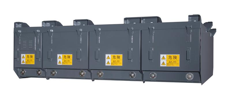 Each housing has a capacity of 120 kWh. Two of these are installed in the Mzc car (two sets). They recover regenerative power and supply power when needed for traction or for sudden changes in APS load.
Figure 7 shows a photograph of the traction battery housing. The traction battery housing has a two-row configuration with a capacity of 120 kWh, and a nominal voltage of 666 V. The housing contains the traction battery modules (lithium-ion batteries), cooling fan, battery unit controllers, integrated battery controller, power supply, electromagnetic contactors [BCK (a) and BCK (b)], service disconnectors, fire extinguishing agent, and fuses. It is charged and discharged according to operating condition of the train.
Each traction battery housing contains a single set and two of these housings are installed in the Mzc car(5).
FCHB Housing
Figure 8—FCHB Housing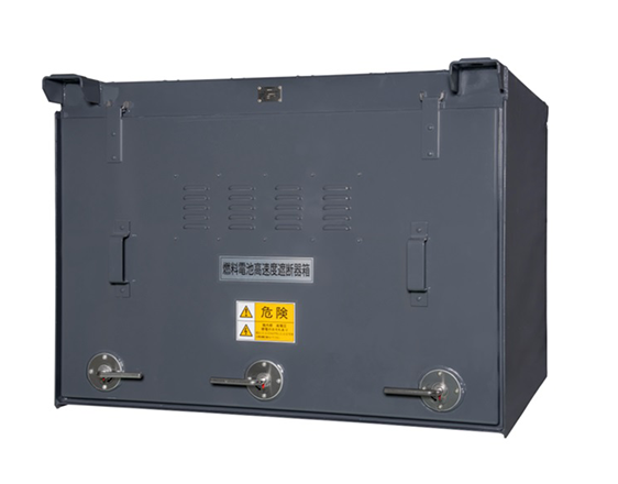 The housing contains the HBs for two fuel cell sets. It is installed in the Tzc car and disconnects the fuel cell from the traction circuit when the protection function is triggered.
Figure 8 shows a photograph of the FCHB housing. It is used to disconnect the fuel cell unit from the power converter in the event of overcurrent in the fuel cell circuit or the triggering of some other protection mechanism. It contains high-speed circuit breakers and electromagnetic contactors, and is used to make and break the traction circuit. No pneumatic air supply is needed for the operation as all of its components are managed by the control circuit power supply.
The FCHB housing contains two circuit breaker sets and installed in the Tzc’ car(5).
Energy Management and Control
Battery Energy Management and Control Practices for Traction Circuit
The hybrid electric car is equipped with a traction battery that is discharged when powering and recharged by regeneration. That is, stored electrical energy is converted to kinetic energy for traction and kinetic energy is converted to stored electrical energy during regeneration. It is based on using electricity generated by the fuel cells to augment the kinetic energy and supply the auxiliary power requirements.
The state of charge (SOC) rises by charging battery and falls by discharging battery. It is used as an indicator with energy management and control being performed in such a way that electricity generated by the fuel cells is used to augment the stored electrical energy as it gets depleted by the auxiliary loads or by extended periods of traction drive(5).
Overview of Generation Control
The fuel cell operation mode on the FV-E991 is based on the diesel hybrid electric car. However, the fuel cells can only deliver an output of up to 120 kW per car, a lot less than the 331-kW output of the engine on a diesel hybrid car. To make up for the electric power consumed by the APS and the depletion of the battery SOC over a typical cycle of acceleration (traction), deceleration (regeneration), and stopping, priority is given to the use of fuel cell power generation during traction. Doing so minimizes the reliance on the traction battery when it is discharging, while using regenerated electric power as the major source of energy during charging with fuel cell generation making up the shortfall. During regeneration, meanwhile, the APS load is supplied by the fuel cell so that all of the regenerated electric power can be recovered by the traction battery to be available the next time it is needed for powering(5).
Overview of Hybrid System Operation
The fuel cell hybrid system was implemented by preferentially using electric power generated by the fuel cell to minimize reliance on the traction battery when discharging, and by using regenerated electric power as a major source of energy when recharging, with fuel cell generation making up the shortfall(5).
- Powering
The train accelerates by drawing electric power from both the fuel cell system and the traction battery [see Figure 9(a)]. - Braking
The regenerative electric power from the inverter is absorbed by the traction battery. The fuel cell system generates electric power to supply the APS load. However, some of the regenerative electric power is diverted to supply the APS to cover the sudden change in load that occurs in situations such as when a compressor starts. This ensures that as much as possible of the electric power regenerated from kinetic energy is supplied to the traction battery. Meanwhile, as the backup APS is not in use at this time, it remains at 0 kW (idling under no load) [see Figure 9(b)]. - Coasting
The fuel cell system generates the electric power to supply the APS load. However, sudden changes in load such as when a compressor starts are supplied by the traction battery. Doing so maintains the traction battery discharge rate as much as possible [see Figure 9(c)].
When the battery SOC becomes depleted, the fuel cell system is used to generate power for charging the traction battery on top of supplying the APS load [see Figure 9(d)].
Figure 9—Operation of Hybrid System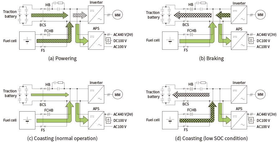 SOC: state of charge (of traction battery) , BCS: traction battery cut-off switchStored electrical energy is converted to kinetic energy when powering, and kinetic energy is converted to stored electrical energy during regenerating. Control is based on using electricity generated by the fuel cells to augment the kinetic energy and supply the auxiliary power requirements.
Conclusions
Trial operation of the FV-E991 testing car has been in progress since March 2022 on the Nambu Line (between Kawasaki and Noborito), Nambu Branch Line (between Shite and Hama-Kawasaki), and the Tsurumi Line (between Tsurumi and Ogimachi) of JR East. Further work on enhancing the practicality of the rolling stock systems is planned, including ongoing trials.
Acknowledgements
Assistance with the development of the traction system for the FV-E991 testing car described in this article was received from large numbers of staff at the East Japan Railway Company, Toyota Motor Corporation, Japan Transport Engineering Company, and other partners. The authors would like to take this opportunity to express their deepest gratitude.
REFERENCES
- 1)
- H. Mitsumoto, et al., “Development of hybrid system for FV-E991 series (HYBARI),” JR EAST Technical Review, No. 69 pp. 11–13 (Mar. 2023) in Japanese.
- 2)
- R. Furuta, et al., “Development of Fuel Cell Hybrid Railcar at East Japan Railway Company,” Rolling stock & technology, No. 129, pp. 2–9 (Feb. 2007) in Japanese.
- 3)
- M. Nakagami, et al., “Development of the First Experimental Fuel Cell Hybrid Railcar in the World” JREA, No. 49 (9), pp. 31892–31895, (Sept. 2006) in Japanese.
- 4)
- H. Nomoto, “Ecological Train – Energy Efficient Vehicle Development Story and Technology,” Sankaido Publishing Co., Ltd., Tokyo (Sept. 2007) in Japanese.
- 5)
- Y. Ohtake, et al., “Fuel Cell Traction System for JR-EAST FV-E991,” Proceedings of 59th Symposium of Congress of Japan Railway Cybernetics, No. 502, (Nov. 2022) in Japanese.