
Type Testing the 420-kV, 63-kA, 50 and 60 Hz EconiQ Circuit-breaker Based on C4-FN/CO2/O2 Gas Mixture Technology
Highlight
Type testing of the world’s first eco-efficient 420-kV circuit breaker (EconiQ), based on a 3.5 mol% C4-FN, 10 mol% O2, and 86.5 mol% CO2 gas mixture, is reviewed here.
The breaker covers the 420 kV / 63 kA ratings (50 and 60 Hz) for both gas-insulated switchgear (GIS) and dead tank breaker (DTB) applications. It adopts two breaking chambers connected in series, one drive per phase, and a kinematic chain for movement transmission. Two standard grading capacitors, connected in parallel to each breaking chamber, evenly distribute the voltage between the two chambers.
The design is robust in terms of mechanical stability, switching and dielectric performance, and the breaker showed excellent performance throughout the development and the type testing campaign, also demonstrating the electrical endurance (E2) capability.
This article describes the most relevant results of the type testing campaign in accordance with the IEC and IEEE standards, including terminal fault, short line fault, high voltage, and capacitive and inductive switching tests.
Introduction
Table 1—Main Ratings of 420-kV Breaker that Uses a C4-FN Mixture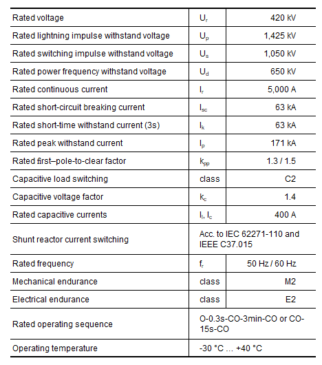 The circuit breaker is based on reliable and well-proven gas circuit breaker technology utilizing the puffer principle, adapted and optimized for the chosen gas mixture.
Figure 1—Breaker (GIS)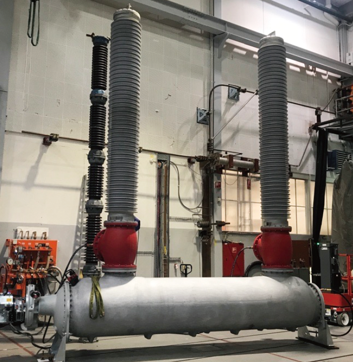 Breaker (GIS) during SLF90 Testing at Accredited STL Laboratory.
The development of eco-efficient circuit breakers represents a very important step towards the reduction of the CO2 footprint of power grids, electrical installations, and transmission systems. After a successful campaign of development tests, the world’s first SF6-free 420-kV circuit breaker, which is based on a 3.5 mol% C4-FN, 10 mol% O2, and 86.5 mol% CO2 gas mixture, was presented at CIGRE(1). Its performance is now fully confirmed by type tests, of which this article presents the key results.
The circuit breaker is based on reliable and well-proven gas circuit breaker technology utilizing the puffer principle, adapted and optimized for the chosen gas mixture. It adopts two breaking chambers connected in series, one drive (spring-hydraulic mechanism) and a robust kinematic chain for movement transmission between the chambers. Two standard grading capacitors, installed in parallel to the breaking chambers, distribute the voltage between them. The design covers both 50 and 60 Hz and both gas-insulated switchgear (GIS) and dead tank breaker (DTB) applications with the same interrupter. The main ratings are reported in Table 1.
To achieve maximum flexibility for application of the breaker in different countries, the test campaign*1 needed to cover both 50 and 60 Hz requirements and both the IEEE (420 kV and in some cases 362 kV(2) , *2) and IEC (420 kV) standards. This required a large number of type tests; therefore, the testing campaign was devised to cover at the same time the greatest number of ratings within the same test shift and to minimize the number of the test objects needed.
In more detail, the test campaign combined:
- Different type tests in a single test shift using the same test object. This was possible due to the excellent breaker design and performance also in worn conditions. The test combinations listed below were selected to optimize the test program for the circuit breaker, including reducing the effort and time needed to change the test circuit in the laboratory. These choices are therefore not indicative of the performance limits of the circuit breaker in terms of electrical wear.
- terminal faults T10-T30-T60,
- shunt reactor current switching tests and a short line fault (SLF75),
- out of phase (OP2) and terminal fault T60,
- terminal fault T100s and service capability.
- Different frequencies. Both IEEE and IEC standards allow some type tests to be performed only at one frequency and still be valid for the other frequency:
- LC (line charging) and CC (cable charging) – 60 Hz test covers 50 Hz since it is more severe.
- Shunt reactor current switching tests – tests at 60 Hz are valid for 50 Hz, tests at 50 Hz are valid for 60 Hz, provided that no re-ignition occurs for arcing times between 8.3 and 10 ms
- T10 and T30 – tests at 60 Hz are valid for 50 Hz and vice versa*3.
- OP2 – tests at 60 Hz are valid for 50 Hz and vice versa.
- Requirements related to different standards (IEEE and IEC). In some cases, they are covered by simply adding a resistance measurement before and after a test and by performing mechanical operations with minimum coil voltages specified in the IEEE standard.
With this efficient strategy, an overall minimization of time and effort was achieved. As an example, a picture of the breaker during an SLF90 test at STL accredited laboratory is shown in Figure 1.
- *1
- All type tests were performed at accredited laboratories that are members of the Short-Circuit Testing Liaison (STL).
- *2
- In IEEE standard C37.04, the 420 kV rating exists only for GIS (Table 7).
- *3
- With conditions on arcing times / current slope at current zero, see Chapter 12 of (3)
Dielectric tests
The SF6 dielectric design process involves optimization of the various breaker parts to fulfill internally developed and widely verified guideline limits. During this process, the electric field (E-field) at each different breaker location is compared to the correct limiting value. The same well-established tools and processes were applied to the new SF6-free breaker, by proper adaptation of the limits to the C4-FN mixture. The internal knowledge built over several years during the study of this and other alternative gases was the key to easily extending the design methodology to cover also C4-FN mixtures(4)(5).
The E-field shielding design of the two-unit concept, as well as the arcing region dielectric design and verifications, were accomplished with the help of both 2D and 3D simulations and optimizations.
Following this process, the first design was achieved extremely efficiently and fast, and already fulfilled the requirements for both lightning impulse (LI) and chopped wave (CW) tests. The type tests confirmed all impulse and AC test duties including partial discharge measurements, where no partial discharge signal above the noise level could be recorded at all required voltage levels.
Capacitive and Shunt Reactor Current Switching Tests
Figure 2—Chopping Number Comparison between SF6 and C4-FN Technologies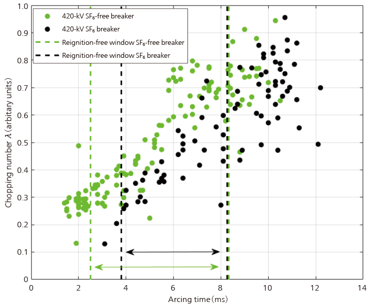 Green circles show the results for the 420-kV SF6-free breaker (133 operations); black circles refer to a 420-kV SF6-puffer breaker (78 operations). The chopping numbers of the two breakers are comparable, the SF6 breaker having a slightly narrower reignition-free window and a larger number of operations with reignition than the SF6-free one. All results are from shunt reactor current switching tests at 60 Hz.
The switching of capacitive loads, such as open transmission lines or cables or capacitor banks used to improve power quality in the high-voltage transmission network, is an important function of high-voltage circuit breakers. The 420-kV SF6-free circuit breaker successfully cleared the line and cable charging switching type tests at 60 Hz, with a capacitive voltage factor kc = 1.4 corresponding to not solidly grounded networks. These tests automatically cover the requirements for solidly grounded networks and 50 Hz and were performed according to the IEC standard and also covering the requirements of the IEEE standard. The strong capacitive switching performance of the 420-kV SF6-free circuit breaker can be attributed in large part to the contribution of the C4-FN molecules in the gas mixture to the overall dielectric strength. Previous studies(6) have clearly demonstrated the important contribution of C4-FN to the dielectric performance for even higher currents than those typically tested for capacitive switching.
The capability to reliably switch inductive loads, needed for the application of the breaker to shunt reactor current switching, was also demonstrated by the SF6-free breaker and it fully satisfies the requirements(7)(8). Since some applications require very frequent switching operations*4, the IEC standard sequence – 78 operations in four test duties(7) – was extended by 55 additional operations. The breaker had an extremely large reignition-free window at 60 Hz, even larger than the already excellent one of existing 420-kV SF6 breakers. Results and comparisons at 60 Hz are shown in Figure 2. The chopping numbers of the SF6 breaker and the SF6-free breaker are similar within the scatter.
The 420-kV SF6-free circuit breaker, with its large reignition-free window and very low likelihood of multiple reignitions occurring during a single power-frequency current-zero crossing, stands in contrast to vacuum circuit breakers*5 . During shunt-reactor switching by a vacuum circuit breaker, a large number of multiple high-frequency reignitions typically occur during many of the switching operations(6). This large number of reignitions and the associated over-voltages (large voltage escalations at multiple high-frequency reignitions(3)) increase the risk of damage to the shunt reactor and other components of the grid during shunt-reactor switching operations(9). The 420-kV SF6-free circuit breaker presents instead a simple, effective, and reliable solution for shunt reactor switching that relies on well-proven gas circuit breaker technology. This circuit breaker is also ideal for the application of controlled switching, since it has a very large reignition-free window, much larger than that of a typical vacuum circuit breaker(6).
- *4
- Thousands of operations are reached in certain cases, e.g., shunt reactor, throughout the life-time of a breaker.
- *5
- Moreover, vacuum interrupters at this voltage level are still under development, and their design (and achieving good SRS performance) might be even more challenging than in sub-transmission ratings.
Terminal Faults
The SF6-free 420-kV circuit breaker successfully passed all the terminal fault tests for 63 kA (T10, T30, T60, T100s, and T100a) defined by the IEC and IEEE standards. The tests were performed in a manner that permitted the requirements of both the IEC and the IEEE standards to be met. The IEC requires a more complex sequence of test operations to be performed, including an open-close-open (O-CO) operation followed within three minutes (if not prevented by the limitations of the test laboratory) by a close-open (CO) operation. The IEEE standard, on the other hand, requires higher transient recovery voltage (TRV) peak values than the IEC standard for the T10 and T30 test duties. Since the IEC standard considers a test with higher voltage than specified to be valid, a test with the IEEE TRV also covers the requirements of the IEC standard. The TRV requirements for the T60, T100s, and T100a tests are the same in both the IEC and IEEE standards.
The minimum arcing times of the circuit breaker were found in all terminal faults to be rather low (comparable or lower than SF6)—illustrating the strong performance of the circuit breaker. Given the short minimum arcing times and opening times provided by the fast drive, interruption can be achieved within two power-frequency cycles.
During the T100s and T100a tests, the maximum short-circuit current must be interrupted by the circuit breaker. As mentioned above, both test duties were successfully passed, for both 50 and 60 Hz. Concerning T100s, part (a) consists of making tests and the breaker demonstrated successfully asymmetrical making with peak factor 3.1, corresponding to 195 kA. Figure 3 shows two examples of successful T100a interruptions of the major loop current at rated asymmetry (134 kA peak, corresponding to a DC time constant of 75 ms) and at intermediate asymmetry during the type tests performed at 50 Hz.
The 420-kV SF6-free circuit breaker has low post-arc currents, less than about 1 A and with a duration of only 10-20 µs(1). These post-arc currents were measured during the L90 test duty, i.e., the worst case, since the steep rise of the line-side voltage after current-zero leads to even higher post-arc currents than during T100s and T100a tests. Recently, it has been shown that vacuum circuit breakers struggle under such conditions(10), in that, even after T100s current interruption, higher post-arc currents (of order 10 A) are measured, which create issues with voltage distribution between chambers in series. It should be noted that in vacuum circuit breakers the dielectric withstand voltage does not scale linearly, but only very slowly, with increasing contact distance(11). Therefore, for vacuum circuit breakers, employing multiple interrupting chambers for higher ratings (above 145 kV) becomes a necessity, rather than an option, with the intrinsic difficulty represented by the high post arc currents.
Figure 3—Example of T100a Test Shots at 50 Hz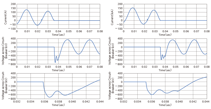 Left-hand plots correspond to first-pole-to-clear, major loop, intermediate asymmetry and right-hand plots to second-pole-to-clear, major loop, rated asymmetry. The top panel illustrates the applied short-circuit current, including the synthetic current injected before the final zero-crossing. The middle and bottom panel show the TRV across the breaker (the recovery voltage phase and a close-up view).
Short Line Faults
The breaker successfully cleared the SLF75 and SLF90 test duties for 63 kA covering IEEE and IEC standards and the initial transient recovery voltage (ITRV) requirements (with less than 100 ns time delay). From the type tests, since all were successful, it would not be possible to say which test, SLF75 or SLF90, has the larger margin. During development tests, though, margins were actively determined by increasing the current derivative at current zero (di/dt) and performing several additional breaking operations, concluding that SLF75 has a larger margin than SLF90. It has been speculated—based on a comparison to air-blast circuit breakers—that the SLF75 test duty may be more severe than the SLF90 test duty for CO2-based circuit breakers(6). However, in the case of the SF6-free 420-kV breaker based on puffer technology, this is contradicted by the obtained results. This is similar to SF6 and in line with expectations, since the 420-kV SF6-free circuit breaker design is based on the reliable puffer SF6 technology and current interruption physics. During type tests, shorter minimum arcing times and higher extinction peaks (see examples at 50 Hz in Figure 4) have been obtained for the SLF75 with respect to the SLF90, for both 50 and 60 Hz. This is also an indication of the better performance of the former.
During all type tests, the breaker showed consistently very short minimum arcing times. This is mostly due to the reliable puffer technology adopted and is an important indication of the breaker performance and clearing capability. A short minimum arcing time allows having shorter medium and maximum arcing times, with less energy input, less ablation, and finally, less wear of the breaker at the end of the tests. This allows a high number of short-circuit switching operations, as also demonstrated by the service capability test.
Figure 4—Arc Voltages during Similar Operations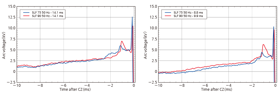 Arc Voltages during Similar Operations in SLF90 and SLF75 at 50 Hz, the latter having larger extinction peaks.
Conclusions
The first eco-efficient 420-kV gas circuit breaker based on a 3.5 mol% C4-FN, 10 mol% O2, and 86.5 mol% CO2 gas mixture was developed at Hitachi Energy and fully type tested, showing excellent performance. The breaker covers both 50 Hz and 60 Hz and was type tested according to both IEEE and IEC standards, covering the more severe requirements for both. The SF6-free breaker also fully demonstrated the extended electrical endurance capability (E2). The breaker is based on a reliable gas circuit breaker technology utilizing the puffer principle. The same technology and tools are currently used to develop the next higher voltage rating aiming the release of world’s first eco-efficient 550-kV circuit breaker in 2024.
REFERENCES
- (1)
- Valeria Teppati, Patrick Stoller, “420 kV C4-FN Circuit Breaker – successful series connection of interrupters,” CIGRE GDM A3 – Q10, Paris, 2 September 2022 (2022).
- (2)
- “IEEE Standard Rating Structure for AC High-Voltage Circuit Breakers,” IEEE Standard C37.04, 2018.
- (3)
- “High-voltage switchgear and controlgear – Part 306: Guide to IEC 62271-100, IEC 62271-1 and other IEC standards related to alternating current circuit-breakers,” IEC TR 62271-306, 2018.
- (4)
- P. C. Stoller, M. Schwinne, J. Hengstler, F. Schober, H. Peters, T. HD. Braun, and W. Albitar. “C5 fluoroketone based gas mixtures as current interrupting media in high voltage switchgear,” Cigré Session 2020. A3-118 (2020).
- (5)
- P. C. Stoller, T. HD. Braun, J. Korbel, S. Buffoni-Scheel, B. Radisavljevic, M. Richter, “SF6 alternative circuit breaker for 145 kV gas insulated switchgear,” Cigré Session 2022. A3-658 (2022).
- (6)
- R. Smeets et al., CIGRE TB 871, “Current Interruption in SF6-free Switchgear,” (2022).
- (7)
- “High-voltage switchgear and controlgear – Part 110: Inductive load switching,” IEC 62271-110, Ed. 4.0, 2017-10.
- (8)
- “IEEE Guide for the Application of Shunt Reactor Switching,” IEEE Standard C37.015, 2009.
- (9)
- Kai Trunk, Andreas Lawall, Erik Taylor, Christian Stiehler, Stephan Wethekam, Thomas Heinz, Jan Weisker, Rene Schaefer, Stefan Giere, “Small inductive current switching with high-voltage vacuum circuit breakers,” pp. 331–334, 29th International Symposium on Discharges and Electrical Insulation in Vacuum (2021).
- (10)
- T. Goebels, P. G. Nikolic, R-M. Cernat, J. Weisker, S. Giere. "Investigation of the switching behaviour, voltage distribution, and post-arc current of series-connected vacuum interrupter units for live tank and dead tank circuit breakers ≥ 420 kV,” Cigré Session 2022. A3-11068 (2022).
- (11)
- P. G. Slade “The Vacuum Interrupter. Theory, Design, and Application,” 2nd Edition. Boca Raton: CRC Press (2022).